
Datasheet

21
XS2
XS2C/XS2G Safety Precautions
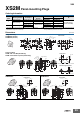
Assembly Procedure for XS2C/XS2G Connector Assemblies
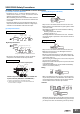
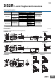
(1) Connector and Cable Diameters
•
Connectors for 8, 7, 6, 4, and 3 mm diameter Cables (i.e.,
Cables that are 7 to 8, 6 to 7, 5 to 6, 4 to 5, and 3 to 4 mm in
diameter respectively) are available.
When assembling a Connector used with a cable, make sure
that the external diameter of the Connector is suited to that
of the cable.
• A waterproof bushing for 6/7 mm diameter Cable has no
stripe, that for 8/4 mm diameter Cable has a single stripe,
and that for 3 mm diameter Cable has two stripes.
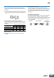
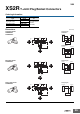
(2) Component Insertion
• As shown in the above illustration, connect the above
components to the Cable with its end processed.
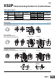
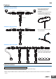
(3) Wiring (Dressing the Cable Ends)
• Strip 10 mm of the Cable sheath and 4 mm of each core.
• Before soldering cores and solder cup pins together, solder-
coat each of them.
• The following conditions are recommended for soldering
each solder cup pin.
Soldering temperature: 350±5°C
Soldering period: 3±1 s
• The length marked *A should be 6.5 mm max., otherwise
the proper degree of protection of the connector will not be
maintained.
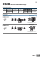
• Strip 14 mm of the Cable sheath and 4 mm of each core.
• Make sure that each core is not damaged and its end
strands are not spread out.
• Mount the XY2F-0003 Locator to XY2F-0002 Crimp Tool,
both of which are sold separately, and set the selector dial
of the Crimp Tool to 8.
• After mounting the crimping pins to the Locator, fully insert
the cores to the crimping pins.
• Squeeze the handle of the Crimp Tool to press-fit the cores
to the crimping pins.
(Squeeze the handle firmly until the handle automatically
returns to the release position.)
• After press-fitting the cores to the pins, insert the pins into
the pin clamp as shown in the illustration. Then make sure
that the lead colors correspond to the pin clamp numbers
that are identical to the connector pin numbers.
• Tentatively insert the pins to the pin block holes so that the
key on the pin block will coincide with the key groove on the
pin clamp. Then insert the cable along with the pin clamp.
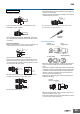
Crimping/Soldering Connectors
Screw-on Connectors
Cover
Watertight
bushing
Cable
clamp
Cap
Cover
Ring (Right-angle models only) *
Watertight
bushing
Cable clamp
Cap
Straight Connectors
Right-angle Connectors
*A ring is not required for Screw-on Connectors.
Cover
Cover
Watertight bushing
Watertight
bushing
Cable clamp
Cable clamp
Cap
Cap
Ring *1
*2
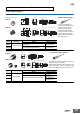
Confirm that you have all of the required parts.
Insulation caps and insulation tubes are included with
5-pole Connectors (XS2C-D5S
@
and XS2G-D5S
@
).
*1. Rings are not required with 7-mm and 8-mm cables.
*2. Insert the waterproof bushing for 7-mm and 8-mm cables in the
direction shown in the diagram.
Soldering Connectors
Crimping Connectors
4
6
6
±0.5
*A
4
10
−0
4
Crimping
Pin clamp
Press
1 to 1.5
Wiring
Pin Block Pin Clamp
Key groove Key groove
Key
XS2C use XS2G use
6
±0.5
Insertion