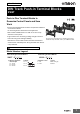
New Product DIN Track Push-in Terminal Blocks XW5T Push-in Plus Terminal Blocks to Downsize Control Panels and Save Work • Push-in Plus terminal blocks are more compact than traditional screw terminal blocks. No loosening means maintenance-free application. • Slim models available down to a width of 3.5 mm to help downsize control panels. • Light insertion force and strong holding strength to achieve both less wiring work and high reliability.
XW5T Part Names and Configuration DIN Track Terminal Block (Top Surface) Basic Configuration Short Bar Nameplate or Labels Terminal (insertion) hole Release hole (to release wire) Short Bar insertion holes • You can attach a Short Bar to either of the two holes. • Insert the tester pins here to perform a continuity check. Label attachment section Note: 1. Do not insert more than one wire into one terminal (insertion) hole. 2. Do not insert more than one Short Bar into one Short Bar insertion hole.
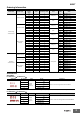
XW5T Ordering Information Classification Product Type Nominal Cross Section (mm2) Number of levels 1.0 1 2 2.5 1 2 Standard terminals Multi tiers terminal Feed Through Terminal blocks Multi conductor terminals Standard terminals Multi tiers terminal Grounding Terminal blocks Multi conductor terminals Number of cramp position per level Color Weight (gram) 3.3 XW5T-P1.5-1.1-1 Dark grey 6.3 XW5T-P2.5-1.1-1 Model 4.0 1 2 8.4 XW5T-P4.0-1.1-1 1.0 1 2 3.3 XW5T-P1.5-1.1-1BL 2.
XW5T For XW5T-P4.0-@ or XW5G-P4.0-@ Appearance No. of poles Colors Model* Application XW5S-P4.0-2@ 2 3 XW5S-P4.0-3@ Red (RD) Blue (BL) Yellow (YL) 4 5 XW5S-P4.0-4@ Used for cross-over wiring between Terminal Blocks. XW5S-P4.0-5@ 10 XW5S-P4.0-10@ * Replace the box (@) in the model number with the code for the covering color. Specify the color: RD = red, BL = blue, YL = yellow Labels Appearance Applicable Terminal Blocks XW5@-P1.5-@ XW5@-P2.5-@ XW5@-P4.
XW5T Ratings and Performance Ratings Feed Through Terminal blocks Standard terminals Model XW5T-P1.5-1.1-1 (BL) XW5T-P2.5-1.1-1 (BL) XW5T-P4.0-1.1-1 (BL) 1 tier, 1:1 1 tier, 1:1 1 tier, 1:1 Applicable wire sizes*1 Appearance and internal wiring NOMINAL CROSS SECTION 1.0 mm2 (1.25 mm2)*2 2.5 mm2 4 mm2 Minimum conductor cross section solid 0.14 mm2 0.14 mm2 0.2 mm2 Maximum conductor cross section solid 1.5 mm2 4.0 mm2 6.0 mm2 Minimum conductor cross section fine stranded 0.08 mm2 0.
XW5T Feed Through Terminal blocks Multi tiers terminal Model XW5T-P1.5-1.1-2 (BL) XW5T-P2.5-1.1-2 (BL) XW5T-P4.0-1.1-2 (BL) 2 tiers, 1:1 2 tiers, 1:1 2 tiers, 1:1 Appearance and internal wiring 1.0 mm2 (1.25 mm2)*2 2.5 mm2 4.0 mm2 Minimum conductor cross section solid 0.14 mm2 0.14 mm2 0.2 mm2 Maximum conductor cross section solid 1.5 mm2 4.0 mm2 6.0 mm2 Minimum conductor cross section fine stranded 0.08 mm2 0.14 mm2 0.2 mm2 Maximum conductor cross section fine stranded 1.5 mm2 2.
XW5T Feed Through Terminal blocks Multi conductor terminals Model XW5T-P1.5-1.2-1 (BL) XW5T-P2.5-1.2-1 (BL) XW5T-P4.0-1.2-1 (BL) 1 tier, 1:2 1 tier, 1:2 1 tier, 1:2 Appearance and internal wiring 1.0 mm2 (1.25 mm2)*2 2.5 mm2 4.0 mm2 Minimum conductor cross section solid 0.14 mm2 0.14 mm2 0.2 mm2 Maximum conductor cross section solid 1.5 mm2 4.0 mm2 6.0 mm2 Minimum conductor cross section fine stranded 0.08 mm2 0.14 mm2 0.2 mm2 Maximum conductor cross section fine stranded 1.5 mm2 2.
XW5T Model XW5T-P1.5-2.2-1 (BL) XW5T-P2.5-2.2-1 (BL) XW5T-P4.0-2.2-1 (BL) 1 tier, 2:2 1 tier, 2:2 1 tier, 2:2 Applicable wire sizes*1 Appearance and internal wiring NOMINAL CROSS SECTION 1.0 mm2 (1.25 mm2)*2 2.5 mm2 4.0 mm2 Minimum conductor cross section solid 0.14 mm2 0.14 mm2 0.2 mm2 Maximum conductor cross section solid 1.5 mm2 4.0 mm2 6.0 mm2 Minimum conductor cross section fine stranded 0.08 mm2 0.14 mm2 0.2 mm2 Maximum conductor cross section fine stranded 1.5 mm2 2.
XW5T Grounding Terminal blocks Standard terminals Model XW5G-P1.5-1.1-1 XW5G-P2.5-1.1-1 XW5G-P4.0-1.1-1 1 tier, 1:1 1 tier, 1:1 1 tier, 1:1 Appearance and internal wiring 1.0 mm2 (1.25 mm2)*2 2.5 mm2 4 mm2 Minimum conductor cross section solid 0.14 mm2 0.14 mm2 0.2 mm2 Maximum conductor cross section solid 1.5 mm2 4.0 mm2 6.0 mm2 Minimum conductor cross section fine stranded 0.08 mm2 0.14 mm2 0.2 mm2 Maximum conductor cross section fine stranded 1.5 mm2 2.5 mm2 4.
XW5T Grounding Terminal blocks Multi tiers terminal Model XW5G-P1.5-1.1-2 XW5G-P2.5-1.1-2 XW5G-P4.0-1.1-2 2 tiers, 1:1 2 tiers, 1:1 2 tiers, 1:1 Appearance and internal wiring 1.0 mm2 (1.25 mm2)*2 2.5 mm2 4.0 mm2 Minimum conductor cross section solid 0.14 mm2 0.14 mm2 0.2 mm2 Maximum conductor cross section solid 1.5 mm2 4.0 mm2 6.0 mm2 Minimum conductor cross section fine stranded 0.08 mm2 0.14 mm2 0.2 mm2 Maximum conductor cross section fine stranded 1.5 mm2 2.5 mm2 4.
XW5T Grounding Terminal blocks Multi conductor terminals Model XW5G-P1.5-1.2-1 XW5G-P2.5-1.2-1 XW5G-P4.0-1.2-1 1 tier, 1:2 1 tier, 1:2 1 tier, 1:2 Appearance and internal wiring 1.0 mm2 (1.25 mm2)*2 2.5 mm2 4.0 mm2 Minimum conductor cross section solid 0.14 mm2 0.14 mm2 0.2 mm2 Maximum conductor cross section solid 1.5 mm2 4.0 mm2 6.0 mm2 Minimum conductor cross section fine stranded 0.08 mm2 0.14 mm2 0.2 mm2 Maximum conductor cross section fine stranded 1.5 mm2 2.5 mm2 4.
XW5T Model XW5G-P1.5-2.2-1 XW5G-P2.5-2.2-1 XW5G-P4.0-2.2-1 1 tier, 2:2 1 tier, 2:2 1 tier, 2:2 Applicable wire sizes*1 Appearance and internal wiring NOMINAL CROSS SECTION 1.0 mm2 (1.25 mm2)*2 2.5 mm2 4.0 mm2 Minimum conductor cross section solid 0.14 mm2 0.14 mm2 0.2 mm2 Maximum conductor cross section solid 1.5 mm2 4.0 mm2 6.0 mm2 Minimum conductor cross section fine stranded 0.08 mm2 0.14 mm2 0.2 mm2 Maximum conductor cross section fine stranded 1.5 mm2 2.5 mm2 4.
XW5T Dimensions (Unit: mm) DIN Track Terminal Blocks XW5T-P1.5-1.1-1 (BL)/XW5G-P1.5-1.1-1 XW5T-P1.5-1.2-1 (BL)/XW5G-P1.5-1.2-1 3.5 3.5 54.1 45 24.5 24.5 30.5 30.5 XW5T-P1.5-2.2-1 (BL)/XW5G-P1.5-2.2-1 XW5T-P1.5-1.1-2 (BL)/XW5G-P1.5-1.1-2 65.7 3.5 33.7 3.5 63.2 35.1 24.5 30.5 30.5 XW5T-P2.5-1.1-1 (BL)/XW5G-P2.5-1.1-1 41.1 24.5 XW5T-P2.5-1.2-1 (BL)/XW5G-P2.5-1.2-1 5.2 5.2 48.8 60.5 29.4 29.4 35.3 35.3 XW5T-P2.5-2.2-1 (BL)/XW5G-P2.5-2.2-1 XW5T-P2.5-1.1-2 (BL)/XW5G-P2.5-1.1-2 5.
XW5T XW5T-P4.0-1.1-1 (BL)/XW5G-P4.0-1.1-1 XW5T-P4.0-1.2-1 (BL)/XW5G-P4.0-1.2-1 6.2 6.2 56.1 66.5 29.4 29.4 35.3 35.3 XW5T-P4.0-2.2-1 (BL)/XW5G-P4.0-2.2-1 XW5T-P4.0-1.1-2 (BL)/XW5G-P4.0-1.1-2 6.2 85 6.2 76.9 40 29.4 35.3 35.3 45.9 29.4 Short Bars XW5S-P1.5-@ 3.5×(No. of poles-1)+2.3 3 Model XW5S-P1.5-2@ 18.2 1.6 3.5 P (mm) 3.5 XW5S-P1.5-3@ 7.0 XW5S-P1.5-4@ 10.5 XW5S-P1.5-5@ 14.0 XW5S-P1.5-10@ 31.5 P XW5S-P2.5-@ 5.2×(No. of poles-1)+3.7 3 Model 23 P (mm) XW5S-P2.
XW5T End Cover XW5E-P1.5-1.1-1 XW5E-P1.5-1.2-1 2.2 2.2 54.1 45 24.5 24.5 XW5E-P1.5-2.2-1 XW5E-P1.5-1.1-2 2.2 65.4 2.2 63.2 35.1 24.5 XW5E-P2.5-1.1-1 XW5E-P2.5-1.2-1 2.2 2.2 48.8 60.5 29.4 29.2 XW5E-P2.5-2.2-1 XW5E-P2.5-1.1-2 2.2 78.8 2.2 72.2 39.8 29.
XW5T XW5E-P4.0-1.1-1 XW5E-P4.0-1.2-1 2.2 2.2 66.5 56.1 29.2 29.4 XW5E-P4.0-2.2-1 XW5E-P4.0-1.1-2 2.2 85 2.2 76.9 39.8 29.2 End Brackets/Separator Plates XW5Z-EP12 (Separator Plates) XW5Z-EP6 (End Brackets) 6 55 12 56 33.5 40.
XW5T Safety Precautions Warning Indications Precautions for Safe Use Precautions for Correct Use Precautions for Correct Use Supplementary comments on what to do or avoid doing, to use the product safely. Supplementary comments on what to do or avoid doing, to prevent failure to operate, malfunction, or undesirable effects on product performance. Precautions for Safe Use • Do not drop the Terminal Block. Terminal Block functionality may be inhibited. • Do not exceed the ratings.
XW5T Connecting Stranded Wires Use the following procedure to connect the wires to the terminal block. 1. Hold a flat-blade screwdriver at an angle and insert it into the release hole. The angle should be between 10° and 15°. If the flat-blade screwdriver is inserted correctly, you will feel the spring in the release hole respond. 2. With the flat-blade screwdriver still inserted into the release hole, insert the wire into the terminal hole until it strikes the terminal block. 3.
XW5T 4. Recommended Ferrules and Crimp Tools Recommended ferrules XW5T-P1.5-@-@@/XW5G-@P1.5-@-@@ Applicable wire Applicable wire (mm2) Ferrule Stripping Recommended ferrules Conductor length Manufactured by Manufactured Manufactured by length (mm) (AWG) Wago (Ferrules used) Phoenix Contact by Weidmuller (mm) 0.14 26 0.25 24 0.34 0.50 0.75 1/1.25 22 20 18 18/17 8 10 AI 0,14-8 H0.14/12 8 10 AI 0,25-8 H0.25/12 10 12 AI 0,25-10 8 10 AI 0,34-8 --H0.34/12 --- --FE-0.25-8N-YE --FE-0.
XW5T Equivalent Labels from Other Companies and Recommended Label Printers Use the following label printer. The following table gives the manufacturer’s model number as of March 2017. Manufacturer Omron Phoenix Contact XW5Z-P1.5LB1 UCT-TM3,5 XW5Z-P2.5LB1 UCT-TM5 Weidmuller 6. Using the Accessories Short Bars Mounting Method Cembre MG-CPM-40 41392 NA MF 8/5 MG-CPM-04 41390N MF 12/5 Label Label printer MF 10/5 MF 10/6 MG-CPM-04 41391 XW5Z-P4.0LB1 UCT-TM6 XW5Z-P1.
XW5T Installation You can bend and cut off any of the middle pins with a tool when you use a Short Bar. Bend. Side-surface Labels Cut. If a Short Bar that has the required pins is not available, you can combine more than one Short Bar to short the required Terminal Blocks. For example, the following figure shows combining Four-pin and Fivepin Short Bars to short eight Terminal Blocks. Shorting 8 Terminal Blocks. 1. Remove the Labels one at a time. 2. Insert them on the sides of the Terminal Blocks.
XW5T End Brackets Mounting Method The mounting and removal methods for DIN Track are the same as those for the Terminal Blocks. Separator Plate Mounting Method Use a flat-blade screwdriver to tighten the screw in the middle of the top surface to mount the Separator Plate. Loosen the screw to remove the Separator Plate from the DIN Track. M4 Screw 7.
Terms and Conditions Agreement Read and understand this catalog. Please read and understand this catalog before purchasing the products. Please consult your OMRON representative if you have any questions or comments. Warranties. (a) Exclusive Warranty. Omron’s exclusive warranty is that the Products will be free from defects in materials and workmanship for a period of twelve months from the date of sale by Omron (or such other period expressed in writing by Omron).
OMRON Corporation Industrial Automation Company Authorized Distributor: Kyoto, JAPAN Contact: www.ia.omron.com Regional Headquarters OMRON EUROPE B.V. Wegalaan 67-69, 2132 JD Hoofddorp The Netherlands Tel: (31)2356-81-300/Fax: (31)2356-81-388 OMRON ELECTRONICS LLC 2895 Greenspoint Parkway, Suite 200 Hoffman Estates, IL 60169 U.S.A. Tel: (1) 847-843-7900/Fax: (1) 847-843-7787 OMRON ASIA PACIFIC PTE. LTD. No.