Cat. No. Z207-E1-03 ZFV Series (Ver 2.
SECTION 1 FEATURES SECTION 2 INSTALLATION & CONNECTION SECTION 3 SETUP SECTION 4 APPENDIX User’s Manual Smart Sensors with Ultra-high-Speed CCD Camera ZFV Series Introduction Section 1 Section 2 Section 3 Section 4 INTRODUCTION APPLICATION CONSIDERATIONS (Please read first)
Introduction Introduction READ AND UNDERSTAND THIS DOCUMENT Please read and understand this document before using the products. Please consult your OMRON representative if you have any questions or comments. WARRANTY OMRON’s exclusive warranty is that the products are free from defects in materials and workmanship for a period of one year (or other period if specified) from date of sale by OMRON.
Introduction Introduction • Nuclear energy control systems, combustion systems, railroad systems, aviation systems, medical equipment, amusement machines, vehicles, safety equipment, and installations subject to separate industry or government regulations. • Systems, machines, and equipment that could present a risk to life or property. Please know and observe all prohibitions of use applicable to the products.
Introduction Precautions for Safe Use Introduction Precautions for Safe Use Please observe the following precautions for safe use of the products. (1) Installation Environment • Do not use the product in environments where it can be exposed to inflammable/ explosive gas. • Install the Amplifier Unit in such a way that the ventilation holes are not blocked. • To secure the safety of operation and maintenance, do not install the product close to high-voltage devices and power devices.
Introduction Precautions for Correct Use Introduction Precautions for Correct Use Please observe the following precautions to prevent failure to operate, malfunctions, or undesirable effects on product performance.
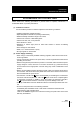
Introduction Precautions for Correct Use Introduction (3) Orientation when Installing the Amplifier Unit To improve heat radiation, install the Amplifier Unit only in the orientation shown below. Right Do not install the Amplifier Unit in the following orientations. Wrong Wrong (4) Maintenance and Inspection • Do not use thinner, benzene, acetone or kerosene to clean the Sensor Head and Amplifier Unit.
Introduction Precautions for Correct Use Introduction Editor's Note Page Format Index label Indicates the section number and title. Title of each section Header Section 3 Setting Banks Overview Setting Banks The ZFV Series can hold up to eight sets of settings. These settings can be switched externally when changing the device setup A set of these settings is called a “bank.” Switching banks BANK 1 is selected as the default. BANK 2 and 8 are also available.
Introduction Editor's Note Introduction ■ Meaning of Symbols Menu items that are displayed on the Amplifier Unit’s LCD screen are indicated enclosed by brackets [aa]. ■ Visual Aids Indicates points that are important to ensure full product performance, such as operational precautions and application procedures. Indicates pages where related information can be found. Indicates information helpful in operation. Indicates functions that can be set only when the setup menu has been switched to EXP menu.
Introduction CONTENTS Precautions for Safe Use 4 Precautions for Correct Use 5 Editor's Note 7 Page Format CONTENTS SECTION 1 7 9 FEATURES 13 ZFV Smart sensor Features 14 Basic Configuration 16 Part Names and Functions 18 SECTION 2 INSTALLATION & CONNECTION 21 About Installation and Connection 22 Amplifier Unit 23 Attaching the ferrite core 23 Installing the Amplifier Unit 23 Gang mounting 27 About the I/O cable 31 Timing charts 34 Sensor Head Introduction Section 1 Sectio
Introduction CONTENTS Introduction SECTION 3 SETUP Setting Flow 42 About Setup 44 Basic Knowledge for Operation 44 List of Setting Items in MENU mode 46 Executing Teaching 48 Teaching Flow 48 Types of Teaching 51 Adjusting Threshold Values 55 Performing Measurement 59 Setting Banks 60 Switching banks 60 Copying banks 60 Clearing banks 60 Setting the bank switching method 60 Setting the System Environment ZFV 61 Adjusting the measurement speed 61 Selecting the measurement
Introduction CONTENTS Customizing Measurement conditions 70 71 Common items 71 PATTERN/SEARCH, MATCH 72 BRIGHT 73 AREA 74 WIDTH 75 POSITION 76 COUNT 77 CHARA/CHARA 1, CHARA 2 78 Saving the Set Measurement Conditions SECTION 4 APPENDIX 82 83 Troubleshooting 84 Error Messages and Remedies 85 Q&A 86 Run Mode Display Item List 87 When Gang-mounting Amplifier Units 89 Gang-mounting example 89 Rules of gang-mounting 90 Data route 91 Teaching process when gang-mounting 92 In
Introduction CONTENTS Introduction 12 MEMO ZFV User’s Manual
Section 1 FEATURES Section 1 FEATURES ZFV Smart sensor Features 14 Basic Configuration 16 Part Names and Functions 18 ZFV User’s Manual 13
Section 1 ZFV Smart sensor Features ZFV Smart sensor Features Section 1 FEATURES The ZFV sensor senses objects by its “surface.” How objects are being sensed can be easily set while verifying on the LCD monitor. The ZFV also incorporates a 250,000-pixel CCD equivalent to that of a Conventional machine vision sensor. This allows presence detection and recognition of different objects, which have up till now been performed visually, to be executed fast and accurately.
Section 1 ZFV Smart sensor Features (3) Business Card-size Amplifier Unit • The Amplifier Unit is designed to be compact so that it can be installed at a wide range of sites. p.95 • Outstanding operate ease has been achieved by a 1.8″color LCD motor, an industryfirst icon-based menu, and simple key layout. Basic Knowledge for Operation p.44 • The ZFV incorporates an extensive range of measurement items which means that numerous applications are supported.
Section 1 Basic Configuration Basic Configuration Section 1 FEATURES The figure below shows the Basic Configuration of the ZFV Series. Sensor Head Detects workpieces as images. • Narrow view type ZFV-SR10 • Wide view type ZFV-SR50 Extension Cord ZFV-XC3BV2(3m)/XC8BV2(8m)/XC3BRV2(3m) Used between a Sensor Head and Amplifier Unit. Two ZFV-XC B(R)V2 cords can be coupled together to extend the cord length.
Section 1 Basic Configuration ● Example 1 In this configuration, multiple parts of an image from a single Sensor Head are measured and multiple inspection item are performed. Section 1 FEATURES Example) Inspection of the number of leads ● Example 2 In this configuration, multiple Sensor heads are used to simultaneously inspect multiple locations on a workpiece. When the TRIG signal is input from a single specified Amplifier Unit, the connected Amplifier Unit starts sensing immediately.
Section 1 Part Names and Functions Part Names and Functions Section 1 FEATURES The following describes the names and functions of parts on the Amplifier Unit and Sensor Head. ■ Amplifier Unit (7) Sensor Head connector (1) OUTPUT indicator (2) RUN indicator (6) LCD monitor (3) Control keys (4) Menu selector switch (5) Mode selector switch (8) Coupler (9) I/O cable (1) OUTPUT indicator The Output indicator lits when the OUTPUT signal turns ON.
Section 1 Part Names and Functions (5) Mode selector switch This switch selects the operating mode. MENU...Select this mode when setting measurement conditions. RUN...Select this mode when performing measurement. Output is performed only when the RUN mode is currently selected. (6) LCD monitor The LCD monitor displays setup menus and images captured from the Sensor Head. (7) Sensor Head connector This connector connects the Sensor Head. (8) Section 1 FEATURES ADJ...
Section 1 Part Names and Functions ■ Sensor Head Section 1 FEATURES (5) Focus adjustment control (1) Lighting part (6) Ventilation film (2) Receiver part (4) Sensor Head mounting fixture (3) Connector (1) Lighting part This section emits light. (2) Receiver part This section captures the image. (3) Connector This connector is connected to the Amplifier Unit. (4) Sensor Head mounting fixture This fixture is for mounting the Sensor Head.
Section 2 INSTALLATION & CONNECTION 22 Amplifier Unit 23 Attaching the ferrite core 23 Installing the Amplifier Unit 23 Gang mounting 27 About the I/O cable 31 Timing charts Sensor Head ZFV User’s Manual 34 37 Attaching the ferrite core 37 Installing the mounting fixture 37 Installing the Sensor Head 38 Connecting the Sensor Head 40 Section 2 INSTALLATION & CONNECTION About Installation and Connection 21
Section 2 About Installation and Connection About Installation and Connection ■ Checking the installation environment Read “Precautions for Safe Use” at the beginning of this manual, and check the installation environment. Section 2 INSTALLATION & CONNECTION 22 ■ Checking the installation site Read “Precautions for Correct Use” at the beginning of this manual, and check the installation site. ■ About the power supply Before installing and connecting the Smart Sensor, be sure to turn it OFF.
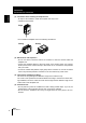
Section 2 Amplifier Unit Amplifier Unit This section describes installation of the Amplifier Unit, and connection of the I/O cable. Before connecting/disconnecting peripheral devices, make sure that the Smart Sensor is turned OFF. The Smart Sensor may break down if the Smart Sensor is connected or disconnected while the power Attaching the ferrite core Attach the ferrite core (provided with the Smart Sensor) to the I/O cable of the Amplifier Unit. Section 2 INSTALLATION & CONNECTION is ON.
Section 2 Amplifier Unit ● Installation procedure 1. Hook the connector end of the Amplifier Unit onto the DIN track. Hook on connector end 2. Push Section 2 INSTALLATION & CONNECTION the Amplifier Unit down onto the DIN track until the hook on the I/O cable side is locked. Push down until you hear it snap into place. Hook on I/O cable Always hook the connector end of the Amplifier Unit on the DIN track first.
Section 2 Amplifier Unit ■ Mounting on a panel The Panel Mount Adapters (sold separately ZS-XPM1) can be used to mount the Amplifier Unit on a panel. Panel Mount Adapters p.100 1. Push out the Amplifier Unit from the rear of Panel 2. Install the small Mount Adapters on the four holes on the Amplifier Unit. Section 2 INSTALLATION & CONNECTION the panel towards the front. Panel Mount Adapter Panel Mount Adapter 3. Install the long Mount Adapters on the two holes on the small Mount Adapter.
Section 2 Amplifier Unit 4. Install the Amplifier Unit with Mount Adapters attached onto the panel from the front. Panel Take care not to pinch the I/O cable. Section 2 INSTALLATION & CONNECTION 5. Hook the hooks of the mounting fixture onto the two holes of the smaller Mount Adapters and tighten the screws. 6. Make sure that the Amplifier Unit is firmly fixed on the panel.
Section 2 Amplifier Unit Gang mounting Up to five Amplifier Units can be gang-mounted. Application Expanded Configuration p.16 Amplifier Units can be easily mounted on the 35-mm DIN track. DIN track (sold separately) PFP-100N (1 m) PFP-50N (0.5 m) PFP-100N2 (1 m) End plate (sold separately) PFP-M ● Installation procedure Section 2 INSTALLATION & CONNECTION ■ Installing on the DIN track 1. Install Amplifier Unit on the DIN track. p.24 2. Open the connector cover on the Amplifier Unit.
Section 2 Amplifier Unit ● Removal procedure 1. Slide the Amplifier Unit, and remove from the connector on the Controller Link Unit. Section 2 INSTALLATION & CONNECTION 28 Controller Link Unit 2. Slide the Controller Link Unit and remove from the connector on the Amplifier Unit. 3. Install the cover on the coupler of the Amplifier Unit. 4. Pull the hook on the I/O cable end downwards. 5. Lift up the Amplifier Unit from the I/O cable end, and remove it from the DIN track.
Section 2 Amplifier Unit ■ Mounting on a panel The Panel Mount Adapters (sold separately ZS-XPM1/XPM2) can be used to mount the Amplifier Unit on a panel. Panel Mount Adapters p.100 p.27 When mounting on a panel, be sure to install the DIN track on the rear side of the Amplifier Unit for support. 2. Push out the Amplifier Unit from the rear of the panel towards the front. Panel Section 2 INSTALLATION & CONNECTION 1. Install the Amplifier Unit on the DIN track. 3.
Section 2 Amplifier Unit 4. Install the long Mount Adapters on the two holes on the small Mount Adapter. Panel Mount Adapters Install the long Mount Adapters only on both sides of gang-mounted Amplifier Units. Section 2 INSTALLATION & CONNECTION Panel Mount Adapters 5. Install the Amplifier Unit with Mount Adapters attached onto the panel from the front. Panel Take care not to pinch the I/O cable. 6.
Section 2 Amplifier Unit About the I/O cable The following shows the leads that comprise the I/O cable. Brown (1) Power supply Blue (2) GND Black (3) OUTPUT* Light blue (5) ERROR Yellow (6) TEACH* Pink (7) TRIG* Gray (8) BANK1* Green (9) BANK2* Red (10) BANK3* Purple White Unused Unused * : Enabled only in the RUN mode (1) Power supply This connects the power supply.
Section 2 Amplifier Unit (6) TEACH (teaching input) There are two teaching modes, workpiece stop teaching and workpiece move teaching. These teaching modes can be selected in the menu. Selecting the teaching mode from an external device (7) p.61 TRIG (measurement trigger input) Section 2 INSTALLATION & CONNECTION There are two measurement modes, synchronous measurement and continuous measurement. Which mode of measurement is to be performed in is selected in the menu.
Section 2 Amplifier Unit Brown Power supply (24VDC) Yellow TEACH Pink TRIG Gray BANK1 Green BANK2 Red BANK3 Blue GND(0V) Light blue ERROR Orange ENABLE Black OUTPUT 24VDC Load Load Load ZFV User’s Manual Section 2 INSTALLATION & CONNECTION Internal circuits ● PNP output type (ZFV-A15/A25) 33
Section 2 Amplifier Unit Timing charts The following shows the timing charts when communication is performed with external devices. Section 2 INSTALLATION & CONNECTION ■ Measurement ● Continuous measurement Measurement is performed continuously for the duration that the TRIG signal is ON. The measurement result is updated, and output to external devices at each measurement cycle.
Section 2 Amplifier Unit ■ Teaching ● Workpiece stop teaching Teaching processing is performed according to TRIG signal input after the TEACH signal is input from the outside. Measurement is not performed while teaching is being performed. Do not move the workpiece until teaching is completed. OFF ON TRIG OFF ON ENABLE OFF ON ERROR OFF ON (1) (8) (4) (5) (2) During teaching processing (6) (7) (1) Turn the TEACH signal ON. (2) Confirm that the ENABLE signal has turned OFF.
Section 2 Amplifier Unit ● Workpiece move teaching Use this teaching mode when the object cannot be stopped. Teaching processing is divided up and performed in synchronous with the TRIG signal input after the TEACH signal is input from the outside. Teaching must be processed six times. Measurement is not performed while teaching is being performed. Section 2 INSTALLATION & CONNECTION Min.
Section 2 Sensor Head Sensor Head This section describes how to install and connect the Sensor Head. Attaching the ferrite core Ferrite core Installing the mounting fixture Attach the mounting fixture (provided with the Smart Sensor) to the side of the Sensor Head. ■ Installation procedure Section 2 INSTALLATION & CONNECTION Attach the ferrite core (provided with the Smart Sensor) to the connector side of the Sensor Head. The mounting fixture can be installed on all of the four mounting surfaces.
Section 2 Sensor Head ■ Removal procedure Insert a regular screwdriver into the gap (one of the two gaps) between the mounting fixture and the Sensor Head case, and remove the mounting fixture. Section 2 INSTALLATION & CONNECTION Mounting fixture Installing the Sensor Head This section describes how to install the Sensor Head. The detection range of the Sensor Head can be confirmed by the guide light. Install so that the part to be inspected is inside the frame formed by the guide light.
Section 2 Sensor Head • ZFV-SR50 Setting distance L (mm) Detection range H (mm) 300 100 9 10 60 Detection range H (mm) 10 38 15 57 20 76 25 95 30 115 35 134 40 157 45 174 50 194 Section 2 INSTALLATION & CONNECTION 30 Setting distance L (mm) (Example) When using a ZFV-SR50 Sensor Head at a detection range of 25 mm required for the location of the sensing object, the setting distance of Sensor Head becomes 95mm.
Section 2 Sensor Head ■ Installation procedure 1. Install the Sensor Head at the installation distance obtained in the above graphs. 2. Turn the focus adjustment control to the left and right to adjust the focus. Focus adjustment control Section 2 INSTALLATION & CONNECTION Focus can be verified by the green guide light. Adjust so that the guide light is fine foned. • Turn to right:Focuses to the far side. • Turn to left:Focuses to the near side. Default is focus set at furthest point.
Section 3 SETUP 42 About Setup 44 Basic Knowledge for Operation List of Setting Items in MENU mode Executing Teaching 44 46 48 Teaching Flow Types of Teaching Adjusting Threshold Values 48 51 55 Performing Measurement 59 Setting Banks 60 Setting the System Environment 61 Adjusting the measurement speed Selecting the measurement timing Selecting the teaching mode from an external device Setting/canceling the “Eco” mode Initializing setup data Initializing measurement data Checking the version C
Section 3 Setting Flow Setting of Measurement Conditions Section 3 SETUP Preparation for Measurement Setting Flow Installation and Connection Set the Sensor Head and Amplifier Unit. SECTION 2 INSTALLATION & CONNECTION p.22 Power ON Adjusting the Image Adjust the focus of the image. SECTION 2 INSTALLATION & CONNECTION p.38 (Only when Amplifier Units are gang-mounted) Settings in an application extended connection Set the processing details for each Amplifier Units.
Additional Functions Setting Banks Use multiple banks for changeover. p.60 Adjusting the measurement speed p.61 Selecting the measurement timing p.61 Selecting the teaching mode from an external device p.61 Setting/canceling the “Eco” mode p.62 Setting Up the System Environment Changing the Input/Output Conditions p.65 Customizing Measurement Conditions p.
Section 3 About Setup About Setup Basic Knowledge for Operation ■ Switching Modes There are 3 operating modes as follows. Switch to the desired mode before you start operation. To switch the operating mode, use the mode switch. Section 3 SETUP Mode Description MENU mode This mode is for executing teaching or setting up the measurement conditions. ADJ mode This mode is for setting the judgment threshold values. RUN mode This mode is for performing actual measurement.
Section 3 About Setup ■ Displays and Key Operations Make setups using the control keys while viewing the menus and the image displayed on the LCD monitor. ● Display The details that are displayed differ according to the operating mode. • MENU mode • ADJ mode/RUN mode Bank No. and measurement item Judgment Settings The currently selected item is displayed inverted.
Section 3 About Setup List of Setting Items in MENU mode The following shows the setting items in MENU mode The details that are displayed differ according to the currently selected setup menu (STD or EXP). Switch the setup menu by the menu selector switch according to your specific requirements. MENU Mode TEACH Setting content ITEM Default value Selection item/Setting range Pages Section 3 SETUP PATTERN - SEARCH, MATCH p.
Section 3 About Setup Setting content [ITEM]:[POSITION] Default value Selection item/Setting range EDGE SENSE NORMAL SENSITIVE, NORMAL, ROUGH COLOR WHITE BLACK, WHITE p.77 p.77 p.79 p.79 p.80 p.
Section 3 Executing Teaching Executing Teaching Execute teaching, and set the measurement conditions. Project the image to be used as the accepted image as the details set in teaching are used as the reference in judgment. Teaching Flow There are two ways of executing teaching, by key operation and by external signals. The following shows a procedure for teaching by key operation Section 3 SETUP For external input teaching p.35 1. Switch to MENU mode. 2.
Section 3 Executing Teaching 6. Press the TEACH key to perform teaching. TEACH/SEARCH ABCDE 1.ITEM 3.SIZE 2.MOVE When changing the teaching area positioning or size, select [MOVE] or [SIZE] from screen 3 then adjust accordingly. [SIZE] Move the area to the position for teaching then press the SET key. Adjust the area size for teaching then press the SET key. TEACH/MOVE ABCDE MOVE Section 3 SETUP [MOVE] TEACH/SIZE ABCDE SIZE Teaching cannot be performed from the MOVE screen or SIZE screen.
Section 3 Executing Teaching ■ Teaching Key Operations and Screen Transition FUN mode top screen Section 3 SETUP ● Teaching execution ● Setting of teaching conditions Setting the teaching details Moving the position of the teaching area Changing the size of the teaching area 50 ZFV User’s Manual
Section 3 Executing Teaching Types of Teaching Select the type of teaching according to the detection content. The details that are displayed differ according to the model of Amplifier Unit that you are using. Detection Content Type of Teaching to Select Pages Pattern/shape/presence PATTERN/SEARCH, MATCH p.51, p.52 Brightness/scratches, dirt BRIGHT p.52 AREA* p.52 Width WIDTH* p.53 Position POSITION* p.53 Number COUNT* p.53 Characters CHARA/CHARA 1, CHARA 2* p.
Section 3 Executing Teaching Item PATTERN MATCH Description Example of Application Select this item for detecting shapes and recognizing differ- Recognition of different kind of instruction ent objects. sheet Judgment is performed by comparing the degree of match between a registered model and the target workpiece. Compared with [SEARCH], more detailed detection is possible, and larger workpieces can be detected. Note, however, that this item does not support tilted workpieces.
Section 3 Executing Teaching Item WIDTH * Description Example of Application Select this item to detect width or interval. Set the teaching area to the part of the workpiece to perform measurement in, and execute teaching. Detection of lead width on capacitors or other electronic components Detection of bent leads Detection of out-ofposition labels Example) To measure width POSITION* Detection of out-ofSelect this item to detect the position of a workpiece.
Section 3 Executing Teaching Item CHARA* CHARA 1 Description Example of Application Select this item to detect the presence of an entire character string printed on a plain background.Judgment is performed by comparing the changes in density (brightness) of a registered character string. Omission of characters, errors, missing dots, etc. cannot be detected.
Section 3 Adjusting Threshold Values Adjusting Threshold Values Threshold values are adjusted to determine the range for OK judgments. Adjust the threshold values referring to the currently indicated measurement results. The adjustment details differ according to the currently set teaching mode. ■ SEARCH, MATCH ● Switch to ADJ Mode. ● Adjustment of correlation value Section 3 SETUP Measured value Correlation value UP/DOWN keys: Change values.
Section 3 Adjusting Threshold Values ■ AREA ● Switch to ADJ Mode. ● Adjustment of area value Binary image Contrast image Can be set on either image. Measured value Section 3 SETUP Upper/lower limit Lower limit Upper limit LEFT/RIGHT keys: Select upper limit/lower limit. UP/DOWN keys: Change values. Setting item Area value Range 0 to 999 Details of Adjustment This is the area in which OK is judged when the area value during teaching is taken to be 100%. ■ WIDTH ● Switch to ADJ Mode.
Section 3 Adjusting Threshold Values ■ POSITION ● Switch to ADJ Mode. ● Adjustment of edge position ● Adjustment of edge level Edge level Measured value Amount of shift Amount of shift UP/DOWN keys: Change values. Edge level UP/DOWN keys: Change values. • When edge detection direction is LEFT/RIGHT keys: Change values.
Section 3 Adjusting Threshold Values ■ CHARA 1 ● Switch to ADJ Mode. ● Adjustment of correlation value Measured value Density distribution value Section 3 SETUP UP/DOWN keys: Setting item Density distribution value Change values. Range 0 to 100 Details of Adjustment This is the value that is judged as OK when the density deviation value during teaching is taken to be 100%. ■ CHARA 2 ● Switch to ADJ Mode.
Section 3 Performing Measurement Performing Measurement When the mode is switched to the RUN mode, measurement is executed, and the measurement result is output to the external device. ■ Switching the display during measurement The display details are switched by pressing the TEACH/VIEW key during measurement. The measurement time differs according to the type of display image. The measurement time for image display” is taken as the reference.
Section 3 Setting Banks Setting Banks The ZFV Series can hold up to eight sets of settings. These settings can be switched externally when changing the device setup. A set of these settings is called a “bank.” Switching banks BANK 1 is selected as the default. BANK 2 and 8 are also available. Section 3 SETUP BANKs can also be switched from an external device. u Bank switching p.36 MENU mode-[BANK] Setting BANK 1 to BANK 8 (default value: BANK 1) Description Selects the target bank.
Section 3 Setting the System Environment Setting the System Environment Adjusting the measurement speed Set the resolution of the input image. Change the resolution according to the required precision and speed of measurement. MENU Mode-[SYS1]-[IMAGE RATE] Setting Description Select this when performing measurement by a high-precision image. Note, however, that it takes longer to perform measurements. NORMAL (default value) Standard HIGH SPEED Select this to perform high-speed measurement.
Section 3 Setting the System Environment Setting/canceling the “Eco” mode Whether or not to darken the screen when a preset time has passed without any operation. We recommend setting this mode to [ON] to prevent the brightness of the LCD screen from being impaired. MENU Mode-[SYS1]-[ECO MODE] Setting Description Section 3 SETUP ON (default value) Sets the “Eco” mode. The screen darkens when three minutes continue without any operation. OFF Cancels the “Eco” mode setting.
Section 3 Setting the System Environment Checking the version Displays the type of Sensor Head, type of Amplifier Unit and system version information of the software. MENU Mode-[SYS2]-[VERSION] Changing image capture timing on teaching screen Section 3 SETUP Select status of image to be displayed in the teaching screen. MENU Mode-[SYS2]-[TEACH IMAGE] Setting Description THROUGH (default value) Display the latest raw image being inputted from the sensor head. FREEZE Freeze the image and display.
Section 3 Setting the System Environment Setting communications environment MENU Mode-[SYS2]-[COM] [MODE] CompoWay/F or no procedures can be set to the communications protocol. Setting Description Section 3 SETUP COMPOWAY (default value) Use this when gang-mounted only with ZFV. This allows communications with external devices using the OMRON proprietary communication protocol CompoWay/F. NORMAL Select when connected to the ZS-DSU for communication without external device procedures.
Section 3 Changing the Input/output Conditions Changing the Input/output Conditions Selecting the ON conditions Set whether to turn the OUTPUT signal ON when OK is judged or when NG is judged. MENU Mode-[SYS2]-[OUTPUT]-[ON STATUS] Setting Description Turns the OUTPUT signal ON when OK is judged. NG ON (default value) Turns the OUTPUT signal ON when NG is judged. Section 3 SETUP OK ON One-shot output OUTPUT turns ON for only the preset output time from when the OUTPUT signal turns ON.
Section 3 Changing the Input/output Conditions ■ Selecting one-shot output ON/OFF Set whether or not to enable one-shot output on the OUTPUT signal. MENU Mode-[SYS2]-[OUTPUT]-[ONE SHOT] Setting Description OFF (default value) One-shot output is not performed. ON One-shot output is performed. When one-shot output is set to [ON], the OFF delay time setting is disabled. Section 3 SETUP ■ Setting the one-shot output time OUTPUT turns ON for the preset time from when the OUTPUT signal turns ON.
Section 3 Changing the Input/output Conditions Setting the OFF delay time Set this item to delay the timing that the OUTPUT signal turns OFF. OUTPUT ON at OK judgment in continuous measurement Judged as NG OUTPUT Judged as OK Judged as NG OFF ON Section 3 SETUP Delay time MENU Mode-[SYS2]-[OUTPUT]-[OFF DELAY] Setting 0 to 255 (default value:0) Description Set the time (ms) to delay turning OFF of the OUTPUT signal.
Section 3 I/O Monitor Function I/O Monitor Function This is a function to check the status of I/O signals. SYS2/I/O MON Signal name : TRIG TEACH : : BANK OUTPUT : ENABLE : ERROR : OK 0 0 000 0 0 1 Signal status (0: OFF, 1:ON) Section 3 SETUP MENU Mode-[SYS2]-[I/O MON] Setting Description TRIG Displays ON/OFF status of TRIG signal. (0:OFF, 1:ON) TEACH Displays ON/OFF status of TEACH signal. (0:OFF, 1:ON) BANK Displays ON/OFF status of BANK signal.
Section 3 Settings During Application Extended Connection Settings During Application Extended Connection These menus are displayed only when Amplifier Units are gang-mounted. Set to the all gang-mounted Amplifier Units.
Section 3 Settings During Application Extended Connection Setting the presence of Sensor Head Set whether or not a Sensor Head is connected. MENU Mode-[SYS2]-[LINKSET]-[HEAD] Setting Description Section 3 SETUP USE (default value) Select this for Amplifier Unit to which a Sensor Head is currently connected. Measurement is performed using the input image from the currently connected Sensor Head. NOT USE Select this for Amplifier Unit to which a Sensor Head is currently not connected.
Section 3 Customizing Measurement conditions Customizing Measurement conditions The display items from [CUSTM] onwards differ according to the teaching type set at [ITEM]. Common items Section 3 SETUP ■ Adjusting light emission Adjust the intensity of the light emitted from Sensor Head. The light intensity of each adjusted section is displayed as a 4-digit number. Top surface (model printed surface) View from here An image of how light is emitted is displayed on screen.
Section 3 Customizing Measurement conditions PATTERN/SEARCH, MATCH ■ Changing the search area Change the area to search the model in. Specify the top left and bottom right of the search area. Search area Model Section 3 SETUP MENU Mode-[CUSTM]-[SEARCH AREA] ■ Setting the rotation range of a workpiece This item is displayed only when [SEARCH] is set. Set this item when even a tilted workpiece is to be set as a non-defective item.
Section 3 Customizing Measurement conditions BRIGHT ■ Changing the detection content Select the content whose brightness is to be detected. MENU Mode-[CUSTM]-[METHOD] Description AVERAGE (default value) Performs detection using brightness (average density value). Whether or not an object is lighter or darker is detected by referring to the density during teaching. DEVIATION Performs detection using sudden changes (density deviation) in density. Select this to detect the presence of scratches or dirt.
Section 3 Customizing Measurement conditions AREA ■ Reversing black-and-white images Reverse the currently displayed binary image. As white pixels are targeted for measurement, select which part of the measured area is to be set to white pixels. MENU Mode-[CUSTM]-[COLOR] Setting WHITE (default value) Description Select which part of the measurement area is to be set as white pixels.
Section 3 Customizing Measurement conditions WIDTH ■ Specifying edge detection conditions Set the direction in which edges are searched and the change in density. Example) Teaching area To detect this width Section 3 SETUP COLOR : BLACK DIRECTION : ● Selecting the color of edges Select the direction of density change for the edge to be detected. MENU Mode-[CUSTM]-[COLOR] Setting Description WHITE (default value) A change from dark to light is judged as an edge.
Section 3 Customizing Measurement conditions POSITION ■ Specifying edge detection conditions Set the direction in which edges are searched and the change in density. Example) To detect this position Section 3 SETUP COLOR : BLACK DIRECTION : ● Selecting the color of edges Select the direction of density change for the edge to be detected. MENU Mode-[CUSTM]-[COLOR] Setting Description WHITE (default value) A change from dark to light is judged as an edge.
Section 3 Customizing Measurement conditions COUNT ■ Specifying edge detection conditions Set the direction in which edges are searched and the change in density. Example) To detect this number Section 3 SETUP COLOR : BLACK DIRECTION : ● Selecting the color of edges Select the direction of density change for the edge to be detected. MENU Mode-[CUSTM]-[COLOR] Setting Description WHITE (default value) A change from dark to light is judged as an edge.
Section 3 Customizing Measurement conditions CHARA/CHARA 1, CHARA 2 ■ Set the model registration conditions for characters This item is displayed only when [CHARA 2] is set. Select the number of characters in the preset teaching area. Select the number of characters being within a certain number of characters on one or two lines.
Section 3 Customizing Measurement conditions ■ Select whether or not to perform Position compensation Set Position compensation for improving detection accuracy in the following instances: When printed text is out of position When there is a pattern in the detection range Setting Description NONE The position is not corrected. MODEL The model is used to correct the position. Select this when there is a characteristics part such as a corner of a text box.
Section 3 Customizing Measurement conditions ● Specifying edge detection conditions Set this when [EDGE] is selected to [MODE]. Set the direction in which edges are searched and the change in density. Example) To correction position by this edge Section 3 SETUP COLOR: BLACK EDGE: • Selecting the color of edges Select the direction of density change for the edge to be detected. MENU Mode-[CUSTM]-[MODE DTL]-[COLOR] Setting Description WHITE A change from dark to light is judged as an edge.
Section 3 Customizing Measurement conditions ■ Changing the search area Change the area to search edges or the model in. Specify the top left coordinate and bottom left coordinate of the area. Search area Search area When searching edges Measurement can be performed only when the search area contains an edge. Determine the size and position of the area taking the movement range of the workpiece into consideration.
Section 3 Saving the Set Measurement Conditions Saving the Set Measurement Conditions The set measurement conditions are saved to the amplifier unit when it is switched to RUN mode. Saving is done automatically, and no confirmation message is displayed. If the power is turned off without saving, the changed contents, including the teaching results, will be cleared from memory. When external TEACH signal teaching is successful in RUN mode, the set measurement conditions are automatically saved.
Section 4 APPENDIX 84 Error Messages and Remedies 85 Q&A 86 Run Mode Display Item List 87 When Gang-mounting Amplifier Units 89 Specifications and External Dimensions 95 Version Up Information 103 INDEX 105 ZFV User’s Manual Section 4 APPENDIX Troubleshooting 83
Section 4 Troubleshooting Troubleshooting This section describes countermeasures for temporary hardware problems. Check the malfunction in this section before sending the hardware for repair. Problem Pages Section 4 APPENDIX OUTPUT indicator does not lit. • Check the setting of [SYS2]-[OUTPUT]-[ON STATUS]. To lit the indicator (OUTPUT signal ON) when the judgment is OK, select [OK ON], and to lit the indicator (OUTPUT signal ON) when the judgment is NG, select [NG ON]. p.
Section 4 Error Messages and Remedies Error Messages and Remedies Error messages Cause Countermeasure Pages BANK DATA ERROR Error in the bank data The bank data will be initialized, and must be reset. - HEAD IS NOT CONNECTED The Sensor Head is not connected correctly. Make sure that the Sensor Head is connected correctly. p.38 NEIGHBOR UNIT IS NOT CONNECTED The Amplifier Units are not coupled correctly. Make sure that the Amplifier Units are connected correctly. p.
Section 4 Q&A Q&A Question Answer Can I turn LED light emission of the Sensor Head OFF? Yes, you can. [CUSTM]-[Set LIGHT] to [0000]. p.71 What should I do to set the measurement time as short as possible? There are two ways of setting a shorter measurement time: • [Set CUSTM]-[IMAGE RATE] to [HIGH SPEED]. Note, however, that image processing becomes rougher, and measurement accuracy drops. p.61 Section 4 APPENDIX • Switch the screen display during measurement to “Display only image”.
Section 4 Run Mode Display Item List Run Mode Display Item List The following tables show the characters that are displayed on the LCD monitor and their meanings Characters in parentheses ( ) are the characters that are displayed in the enlarged display mode. ■ Items displayed in common at [ITEM] Display Characters Meaning AVE Average value of measurement result DRANGE Min. and max. of measurement result XX – YY (min. value – max.
Section 4 Run Mode Display Item List ● COUNT Display Characters COUNT(CNT) Meaning Count ● CHARA 1 Display Characters DENDEV(DEV) Section 4 APPENDIX 88 ZFV User’s Manual Meaning Density distribution value
Section 4 When Gang-mounting Amplifier Units When Gang-mounting Amplifier Units Application examples of amplifier unit gang-mounting and caution notes are explained. Gang-mounting example ■ 1 sensor head + multiple amplifier units Example of detection of input image from 1 sensor head with multiple amplifier units. •To detect multiple areas such as a 4-sided POSITION, multiple item SEARCH, etc. •To detect multiple types such as both SEARCH and AREA judgments.
Section 4 When Gang-mounting Amplifier Units Rules of gang-mounting Item Rules No. of Amplifier Units connectable Maximum 5 No.
Section 4 When Gang-mounting Amplifier Units Data route ■ Measurement image The measurement image flows from the right-side amplifier unit towards the left-side. Image input timing delays do not occur. The TRIG signal flows from the right-side amplifier unit towards the left-side. Input timing delays do not occur.
Section 4 When Gang-mounting Amplifier Units Teaching process when gang-mounting ■ Teaching (key input) from MENU Mode Enter the teaching screen from the host device and press the TEACH key to teach all clients in the teaching screen where the host device is added. Enter the teaching screen for the client only and press the TEACH key to teach only this client.
Section 4 When Gang-mounting Amplifier Units Integrating judgment output Judgment result output (OUTPUT) of gang-mounted amplifier units can be integrated. Setting output content p.70 ■ When all amplifier unit measurement results are integrated (ALL) Select [ALL] to integrate measurement results of all gang-mounted amplifier units and output from amplifier units (host device) where TRIG signals are input. Obtain OUTPUT signal after ENABLE signal is set to ON.
Section 4 When Gang-mounting Amplifier Units Restrictions when gang-mounting old and new amplifier units Restrictions on gang-mounting between ZFV-A units are explained. The amplifiers below (hereinafter new amplifiers) and amplifiers with serial numbers previous to this (hereinafter old amplifiers) cannot be gang-mounted. ZFV-A10 SER No.0863Y04 or later ZFV-A15 SER No.0060Y04 or later ZFV-A20 SER No.0834Y04 or later ZFV-A25 SER No.
Section 4 Specifications and External Dimensions Specifications and External Dimensions Sensor Head ZFV-SR10/SR50 (Unit: mm) 20 2-M4 depth 6 17.9 34 1/4-20 UNC depth 6 Mounting hole dimensions 2-M4 33 Mounting fixture can be attached on each side. 20 32 4.5 67.9 4.5 17.9 5.6 12.8 dia. 32 33.6 4.5 30 Heat-resistant PVC shielded cable 5.8 mm dia. standard length 2 m 4.5 8.5 0.1 (6.36) 4 30 Section 4 APPENDIX 30.1 (6.36) 23.
Section 4 Specifications and External Dimensions Item ZFV-SR10 (Narrow View) Setting distance (L) 34 to 49 mm 38 to 194 mm Detection range (H×V) 5 × 4.6 mm to 9 × 8.3 mm 10 × 9.2 mm to 50 × 46 mm Relation between setting distance and detection range Setting distance (L) Setting distance (L) 49mm 194mm 34mm 38mm 5mm Section 4 APPENDIX 96 ZFV-SR50 (Wide View) 9mm Detection range (H) 10mm 50mm Detection range (H) Guide light Provided (center, sensing area) Built-in lens Focus: f15.
Section 4 Specifications and External Dimensions Amplifier Unit ZFV-A (Unit: mm) 23.2 60 4.6 90 3.9 18 Section 4 APPENDIX 90 23.4 4.2 14.8 Heat-resistant PVC shielded cable 5.2 mm dia. standard length 2 m. 52.5 11.7 dia.
Section 4 Specifications and External Dimensions Single-function Models Item Section 4 APPENDIX 98 ZFV-A10 Standard Models ZFV-A15 PNP ZFV-A20 NPN ZFV-A25 Output method NPN Output specifications NPN: NPN open-collector, 30 VDC, 50 mA max., residual voltage: 1.2 V max. PNP: PNP open-collector, 50 mA max., residual voltage: 1.2 V max. PNP Input specifications NPN: At ON: maximum 0V short circuit or maximum 1.5V, At OFF: open circuit (Leakage current at maximum 0.
Section 4 Specifications and External Dimensions Item Single-function Models ZFV-A10 ZFV-A15 Ambient humidity Operating and storage: 35% to 85% Ambient atmosphere Must be free of corrosive gas. Degree of protection IEC60529, IP20 Materials Polycarbonate Weight Approx.
Section 4 Specifications and External Dimensions Panel Mount Adapters ZS-XPM1/XPM2 When mounting on a panel (60 n)+12 60 n (Unit: mm) 13 3 Panel (140) 90 122 DIN track Section 4 APPENDIX Panel Panel Mount Adaptor (2) (37.5) (Note 1) Note 1 : Dimensions are shown for a panel thickness of 2.0 mm.
Section 4 Specifications and External Dimensions Control Link Unit ZS-XCN (Unit: mm) 11.50 18 13.40 Section 4 APPENDIX 39.50 Item Ambient temperature 4.60 ZS-XCN Operating: 0 to 50°C, Storage: -15 to +60°C (with no icing or condensation) Ambient humidity Operating and storage: 35% to 85% (with no condensation) Vibration resistance (destructive) 10 to 150 Hz, 0.
Section 4 Specifications and External Dimensions Extension Cord ZFV-XC B(R)V2 (Unit: mm) L (Note 1) 75 13 8.5 45.9 3.5 28 30 36 2- 33 Mounting holes 20 pins Section 4 APPENDIX PVC insulated round cable: 28 0.
Section 4 Version Up Information Version Up Information Software version upgrade contents are explained. ■ Ver1.00 Ver2.00 Changes A function for logging measurement images and measurement values together when connecting to the data storage unit type ZS-DSU added Reference * p.62 A function for setting teaching screen image capture timing added p.63 A function for setting the communications environment added p.64 An I/O monitor function (Function to check I/O signal status) added p.68 Added p.
Section 4 Version Up Information Section 4 APPENDIX 104 ZFV User’s Manual
Section 4 INDEX INDEX A E ECO MODE 62 “Eco” mode 62 Edge 75 Color of edges 75, 76, 77 detectivity 76 Edge detection direction 75, 76, 77 Edge level 56, 57 EDGE SENSE 76 Edge width 56 Expert menu 44 Extension cord 102 B BANK 60 Bank 60 bank extension 15 Clearing banks 60 Copying banks 60 Setting the bank switching method 60 Switching banks 60 Binarization 74 BINARY 74 Section 4 APPENDIX ADJ mode 44 Adjusting light emission 71 ALL CLEAR 62 Amplifier Unit 23 Attaching the ferrite core 23 Installing the Am
Section 4 INDEX Gang mounting Panel Installation distance 27 25 38 Key Operations 45 Continuous measurement Output time Synchronous measurement Operating modes OUTPUT OUTPUT TIME K 65 66 65 44 68, 70 66 P L LIGHT Logging 71 15 M Section 4 APPENDIX MDL DIV 78 MEAS CLEAR 62 MEAS TYPE 61 Measurement 59 Adjusting the measurement speed 61 Measurement time 59 Measurement timing 61 Switching the display during measurement 59 MENU mode 44 Description of MENU mode 44 List of Setting Items 46 Menu selector
Section 4 INDEX Section 4 APPENDIX BRIGHT 52 CHARA 54 COUNT 53 PATTERN 51 POSITION 53 Teaching Flow 48 Types of Teaching 51 WIDTH 53 Workpiece move teaching 36 Workpiece stop teaching 35 Teaching Key Operations and Screen Transition 50 Threshold Values 55 AREA 56 BRIGHT 55 CHARA 1 58 CHARA 2 58 COUNT 57 MATCH 55 POSITION 57 SEARCH 55 WIDTH 56 THROUGH 63 Timing charts 34 Continuous measurement 34 Synchronous measurement 34 TRIG 69 V VERSION Version 63 63 Wide View 96 W ZFV User’s Manual 107
4_end.FM Page 108 Tuesday, September 12, 2006 5:54 PM Section 4 Revision History Revision History A manual revision code appears as a suffix to the catalog number at the bottom of the front and back covers of this manual. Cat. No. Z207-E1-03 Revision code Revision code Section 4 APPENDIX 108 Date Revised contents 01 August 2004 Original production 02 March 2005 Functions added as per software version upgrade (Ver2.
Z207-E1-03 ZFV Series (Ver 2.0) OMRON Corporation Industrial Automation Company Sensing Devices Division H.Q. Application Sensors Division Shiokoji Horikawa, Shimogyo-ku, Kyoto, 600-8530 Japan Tel: (81)75-344-7068/Fax: (81)75-344-7107 Regional Headquarters OMRON EUROPE B.V. Sensor Business Unit, Carl-Benz-Str. 4, D-71154 Nufringen, Germany Tel: (49)7032-811-0/Fax: (49)7032-811-199 OMRON ELECTRONICS LLC 1 East Commerce Drive, Schaumburg, IL 60173 U.S.A.