
User's Manual
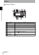
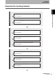
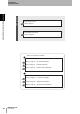
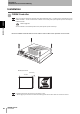
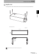
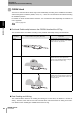
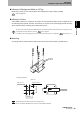
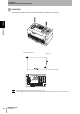
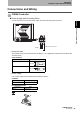
Table Of Contents
- Read and Understand this Manual
- Warranty
- Limitations of Liability
- Suitability for Use
- Programmable Products
- Change in Specifications
- Dimensions and Weights
- Errors and Omissions
- Applicable Standards
- Applicable SEMI Standards
- Precautions for Safe Use
- Precautions for Correct Use
- Editor’s Note
- Table of Contents
- What is a CIDRW System?
- Features
- System Configuration
- Component Names and Functions
- Flowchart for Getting Started
- Installation
- Connections and Wiring
- Set the Communications Conditions for the CIDRW Controller
- Set the Communications Conditions for Amplifier Units
- Set the Communications Conditions for Link Units
- Communications Test
- When SECS is Used
- When SECS is Not Used
- When SECS is Used
- When SECS is Not Used
- Specifications and Dimensions
- Data Segment Area
- Regular Inspection
- SECS Protocol Specifications
- ASCII Code Table
- Protective Construction

28
SECTION 2
Installation
CIDRW System
User’s Manual
SECTION 2
Installation and Connections/Wiring
CIDRW Head
The area for communications with ID Tags varies substantially according to the installation orientations
and the background conditions (metals, noise, etc.). Check the communications area before deciding
the installation position.
For details on actual communications distances, see Characteristic Data depending on Conditions of
Use in Appendix.
Refer to page 109.
Positional Relationship between the CIDRW Head and the ID Tag
The communications area differs according to the positional relationship during communications.
Data Reading and Writing
The communications distances for reading and writing are not the same; the distance is shorter for
writing. Therefore, when data is to be both read and written, take the distance for writing as the refer-
ence distance when installing the CIDRW Head and the ID Tag.
Mounting
orientation
Communications area (purely illustrative) Explanation
Coaxial The maximum communications area is
obtained when the centerlines of the CIDRW
Head and the ID Tag coincide.
Parallel The maximum communications area is
obtained when the center point of the
antenna on the CIDRW Controller is aligned
with the centerline of the ID Tag.
Vertical When the center point of the antenna on the
CIDRW Head is aligned with the centerline of
the ID Tag, the communications area is sub-
stantially reduced.