
User's Manual
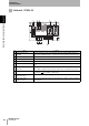
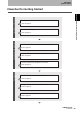
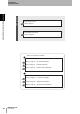
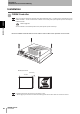
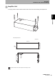
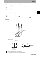
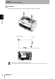
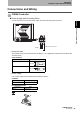
Table Of Contents
- Read and Understand this Manual
- Warranty
- Limitations of Liability
- Suitability for Use
- Programmable Products
- Change in Specifications
- Dimensions and Weights
- Errors and Omissions
- Applicable Standards
- Applicable SEMI Standards
- Precautions for Safe Use
- Precautions for Correct Use
- Editor’s Note
- Table of Contents
- What is a CIDRW System?
- Features
- System Configuration
- Component Names and Functions
- Flowchart for Getting Started
- Installation
- Connections and Wiring
- Set the Communications Conditions for the CIDRW Controller
- Set the Communications Conditions for Amplifier Units
- Set the Communications Conditions for Link Units
- Communications Test
- When SECS is Used
- When SECS is Not Used
- When SECS is Used
- When SECS is Not Used
- Specifications and Dimensions
- Data Segment Area
- Regular Inspection
- SECS Protocol Specifications
- ASCII Code Table
- Protective Construction

31
CIDRW System
User’s Manual
SECTION 2
Connections and Wiring
SECTION 2
Installation and Connections/Wiring
Connections and Wiring
CIDRW Controller
Power Supply and Grounding Wires
Connect the wires to the 24 VDC power supply terminals and frame ground terminal.
• Crimp terminals
The terminal screws on the terminal block are M3 size. Use appropriate crimp terminals for M3 screws
as shown below.
• Power supply
Use a power supply unit that satisfies the following conditions.
Be sure to replace the cover after wiring.
Crimp terminals
Shape Size
Forked
Round
Condition
Power supply voltage Output current
24 VDC +10%, -15% 500 mA DC min.
Recommended model
Manufacturer Model
OMRON S82K-01524
Ground to 100 Ω or less.
24 VDC
6 mm max.
6 mm max.