
User's Manual
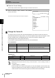
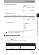
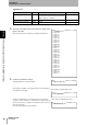
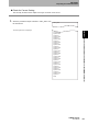
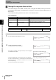
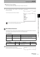

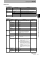

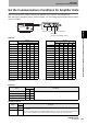
Table Of Contents
- Read and Understand this Manual
- Warranty
- Limitations of Liability
- Suitability for Use
- Programmable Products
- Change in Specifications
- Dimensions and Weights
- Errors and Omissions
- Applicable Standards
- Applicable SEMI Standards
- Precautions for Safe Use
- Precautions for Correct Use
- Editor’s Note
- Table of Contents
- What is a CIDRW System?
- Features
- System Configuration
- Component Names and Functions
- Flowchart for Getting Started
- Installation
- Connections and Wiring
- Set the Communications Conditions for the CIDRW Controller
- Set the Communications Conditions for Amplifier Units
- Set the Communications Conditions for Link Units
- Communications Test
- When SECS is Used
- When SECS is Not Used
- When SECS is Used
- When SECS is Not Used
- Specifications and Dimensions
- Data Segment Area
- Regular Inspection
- SECS Protocol Specifications
- ASCII Code Table
- Protective Construction

53
CIDRW System
User’s Manual
SECTION 3
Set the Communications Conditions for the CIDRW Controller
SECTION 3
Preparing for Communications
1. Specify the parameters to be changed.
When the first parameter is specified, the ALARMS indicator flashes.
2. Confirm the parameter change.
The input parameter is checked and written.
Check for Correct Setting
The currently set data can be output so that you can check if it is correct.
1. Send the parameter output command "::GET_E99SYS"
from the host device.
The carrier ID settings are displayed.
Do not change operation parameters other than RT, CIDOF, and CIDLN.
This can cause the system to stop operating correctly.
Change the data segment area
The data segment area (memory map) must be changed to communicate with ID Tags (RI-TRP-DR2B,
made by Texas Instruments). The procedure for changing the data segment area is explained here.
Data Segment Area Refer to page 122.
The commands, and the parameters that can be set, are indicated below.
List of Commands
Designation Command input Explanation
Parameter designation (Tag name) = (Set value) <CRLF> Specify the parameter value corresponding to the tag name.
Parameter confirmation ::END Checks the parameter designations that have been received so
far and, if there is no error, confirms the settings.
Comment # (Comment) <CRLF>
or
CRLF
This is ignored as the comment line.
CIDOF=0
CIDLN=16
::END
_
::GET_E99SYS
RT=10.0
CT=0.1
RTY=3
DINST=
MENT=
MODEL=L22
HREV=001.04
CIDOF=00
CIDLN=16
::END
_