
Computer Hardware User Manual


300
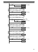
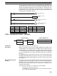
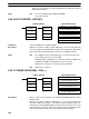
00000 LD 00001
00001 SNXT(09) LR 0000
00002 SNXT(09) LR 0002
00003 STEP(08) LR 0000
Process A
00100 LD 00002
00101 SNXT(09) LR 0001
00102 STEP(08) LR 0001
Process B
00200 LD LR 0003
00201 OUT LR 0003
00202 AND 00004
00203 SNXT(09) LR 0004
00204 STEP(08) LR 0002
Process C
00300 LD 00003
00301 SNXT(09) LR 0003
00302 STEP(08) LR 0003
Process D
00400 STEP(08) LR 0004
Process E
00500 LD 00005
00501 SNXT(09) LR 0005
00502 STEP(08) ---
Address Instruction Operands Address Instruction Operands
5-25 Special Instructions
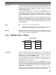
The instructions in this section are used for various operations, including pro-
gramming user error codes and messages, counting ON bits, setting the watch-
dog timer, and refreshing I/O during program execution.
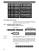
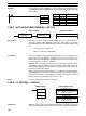
5-25-1 FAILURE ALARM – FAL(06) and
SEVERE FAILURE ALARM – FALS(07)
N: FAL number
# (00 to 99)
Ladder Symbols Definer Data Areas
@FAL(06) NFAL(06) N
N: FAL number
# (01 to 99)
FALS(07) N
Limitations FAL(06) and FALS(07) share the same FAL numbers. Be sure to use a number
in either FAL(06) or FALS(07), not both.
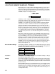
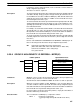
Description FAL(06) and FALS(07) are provided so that the programmer can output error
numbers for use in operation, maintenance, and debugging. When executed
with an ON execution condition, either of these instructions will output a FAL
number to bits 00 to 07 of SR 253. The FAL number that is output can be be-
tween 01 and 99 and is input as the definer for FAL(06) or FALS(07). FAL(06)
with a definer of 00 is used to reset this area (see below).
25307 25300
X10
1
X10
0
FAL Area
Special Instructions Section 5-25