
Computer Hardware User Manual

334
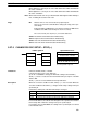
S Function
Word
address
The contents of S through S+4 are copied to the part of the PC Setup
that contains the settings for the port specified by N.
Constant
(#0000)
The settings for the port specified by N are returned to their default val-
ues.
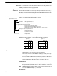
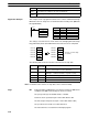
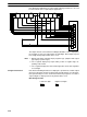
Application Example This example shows a program that transfers the contents of DM 0100 through
DM 0104 to the PC Setup area for Communications Board port A (DM 6555
through DM 6569).
@STUP(––)
001
DM 0100
000
00000
Address Instruction Operands
00000 LD 00000
00001 @STUP(––)
001
DM 0100
000
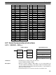
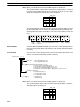
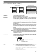
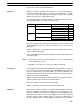
The settings are transferred as shown below. The Changing RS-232C Setup
Flag (SR 27504) will be turned OFF when the transfer has been completed.
DM 0100
DM 0101
DM 0102
DM 0103
DM 0104
1001DM 6555
0803DM 6556
0000DM 6557
2000DM 6558
0000DM 6559
1001
0803
0000
2000
0000
1001
0803
0000
2000
0000
1001
0803
0000
2000
0000
1001
0803
0000
2000
0000
1001
0803
0000
2000
0000
1001
0803
0000
2000
0000
1001
0803
0000
2000
0000
(Refer to 3-6-4 PC Setup
for details.)
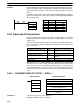
The following table shows the function of the transferred setup data.
Word Content
(see note)
Function
DM 0100 1001 Enables the communications settings in DM 0101 and
sets the communications mode to RS-232C.
DM 0101 0803 Sets the following communications settings:
9,600 bps, 1 start bit, 8-bit data, 1 stop bit, no parity
DM 0102 0000 No transmission delay (0 ms)
DM 0103 2000 Enables the end code CR, LF.
DM 0104 0000 ---
Note For details on the contents of setup data, refer to 3-6-4 PC Setup.
Flags ER: Indirectly addressed DM word is non-existent. (Content of DM word is
not BCD, or the DM area boundary has been exceeded.)
The port specifier (N) isn’t IR 000, IR 001, or IR 002.
Port A has been specified, but pin 2 of the DIP switch is ON.
The PC Setup is write-protected. (Pin 1 of the DIP switch is ON.)
The specified source words exceed the data area.
The instruction was executed from an interrupt program.
Serial Communications Instructions Section 5-27