
Garage Door Opener User Manual


26
3-1 Introduction
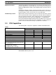
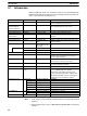
Details, including the name, size, and range of each area are summarized in the
following table. Data and memory areas are normally referred to by their acro-
nyms, e.g., the IR Area, the SR Area, etc.
Area Size Range Comments
I/O Area 480 bits IR 000 to IR 029 I/O words are allocated to the CPU Rack and
Expansion I/O Racks by slot position.
1
Group-2 High-density
I/O Unit and B7A
Interface Unit Area
320 bits IR 030 to IR 049 Allocated to Group-2 High-density I/O Units and
to Group-2 B7A Interface Units 0 to 9
1
SYSMAC BUS Area 800 bits IR 050 to IR 099 Allocated to Remote I/O Slave Racks 0 to 4.
1
Special I/O Unit Area 1,600 bits IR 100 to IR 199 Allocated to Special I/O Units 0 to 9.
1
Optical I/O Unit and I/O
Terminal Area
512 bits IR 200 to IR 231 Allocated to Optical I/O Units and I/O
Terminals.
1
Work Area 1 64 bits IR 232 to IR 235 For use as work bits in the program.
Special Relay Area 1 312 bits SR 23600 to SR
25507
Contains system clocks, flags, control bits, and
status information.
Special Relay Area 2 704 bits SR 256 to SR 299
(298 to 299 reserved
by system)
Contains flags, control bits, and status informa-
tion.
Macro Area
64 bits SR 290 to SR 293 Inputs
64 bits SR 294 to SR 297 Outputs
Work Area 2 3,392 bits IR 300 to IR 511 For use as work bits in the program.
Temporary Relay Area 8 bits TR 00 to TR 07 Used to temporarily store and retrieve execution
conditions when programming certain types of
branching ladder diagrams.
Holding Relay Area 1,600 bits HR 00 to HR 99 Used to store data and to retain the data values
when the power to the PC is turned off.
Auxiliary Relay Area 448 buts AR 00 to AR 27 Contains flags and bits for special functions. Re-
tains status during power failure.
Link Relay Area 1,024 bits LR 00 to LR 63 Used for data links in the PC Link System.
1
Timer/Counter Area 512 counters/
timers
TC 000 to TC 511 Used to define timers and counters, and to
access completion flags, PV, and SV.
Interval timers 0 through 2 and high-speed
counters 0 through 2 provided in separate area.
TIM 000 through TIM 015 can be refreshed via
interrupt processing as high-speed timers.
Data Memory Area
6,144 words DM 0000 to DM 6143 Read/Write
y
1,000 words DM 0000 to DM 0999 Normal DM.
1,000 words DM 1000 to DM 1999 Special I/O Unit Area
2
4,000 words DM 2000 to DM 5999 Normal DM.
31 words DM 6000 to DM 6030 History Log
(44 words) DM 6100 to DM 6143 Link test area (reserved)
Fixed DM Area
512 words DM 6144 to DM 6599 Fixed DM Area (read only)
56 words DM 6600 to DM 6655 PC Setup
Expansion DM Area 3,000 words max. DM 7000 to DM 9999 Read only
Note 1. These can be used as work words and bits when not used for their allocated
purposes.
2. The PC Setup can be set to use DM 7000 through DM 7999 as the Special
I/O Area.
Introduction Section 3-1