Cat. No.
CS1W-ETN01 (10Base-5) CS1W-ETN11 (10Base-T) CJ1W-ETN11 (10Base-T) Ethernet Units Operation Manual Revised January 2008
iv
Notice: OMRON products are manufactured for use according to proper procedures by a qualified operator and only for the purposes described in this manual. The following conventions are used to indicate and classify precautions in this manual. Always heed the information provided with them. Failure to heed precautions can result in injury to people or damage to property. !DANGER Indicates an imminently hazardous situation which, if not avoided, will result in death or serious injury.
vi
TABLE OF CONTENTS PRECAUTIONS . . . . . . . . . . . . . . . . . . . . . . . . . . . . . . . . xvii 1 Intended Audience . . . . . . . . . . . . . . . . . . . . . . . . . . . . . . . . . . . . . . . . . . . . . . . . . xviii 2 General Precautions . . . . . . . . . . . . . . . . . . . . . . . . . . . . . . . . . . . . . . . . . . . . . . . . xviii 3 Safety Precautions. . . . . . . . . . . . . . . . . . . . . . . . . . . . . . . . . . . . . . . . . . . . . . . . . .
TABLE OF CONTENTS SECTION 4 System Setup and Memory Allocations. . . . . . . . . . . . . . 57 4-1 Allocated Words . . . . . . . . . . . . . . . . . . . . . . . . . . . . . . . . . . . . . . . . . . . . . . . . . . 58 4-2 CPU Bus Unit System Setup . . . . . . . . . . . . . . . . . . . . . . . . . . . . . . . . . . . . . . . . . 59 4-3 CIO Area Allocations . . . . . . . . . . . . . . . . . . . . . . . . . . . . . . . . . . . . . . . . . . . . . . 67 4-4 DM Area Allocations. . . . . . . . . . . . .
TABLE OF CONTENTS SECTION 10 Troubleshooting . . . . . . . . . . . . . . . . . . . . . . . . . . . . . . . . 191 10-1 Troubleshooting with Indicators . . . . . . . . . . . . . . . . . . . . . . . . . . . . . . . . . . . . . . . 192 10-2 Error Status . . . . . . . . . . . . . . . . . . . . . . . . . . . . . . . . . . . . . . . . . . . . . . . . . . . . . . . 194 10-3 Error Log. . . . . . . . . . . . . . . . . . . . . . . . . . . . . . . . . . . . . . . . . . . . . . . . . . . . . . . . .
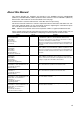
About this Manual: This manual describes the installation and operation of the SYSMAC CS-series CS1W-ETN01 (10Base-5) and CS1W-ETN11 (10Base-T) Ethernet Units and the CJ-series CJ1W-ETN11 (10Base-T) Ethernet Unit, and includes the sections described on the next page. An Ethernet Unit is classified and treated as a CPU Bus Unit in PC processing. This manual is based on Ethernet* networks comprised of Ethernet Unit nodes and UNIX* host computer nodes.
About this Manual, Continued Name Cat. No. Contents SYSMAC CS/CJ-series C200H-PRO27-E, CQM1H-PRO01-E CQM1-PRO01-E Programming Consoles Operation Manual W341-E1-@ Provides information on how to program and operate CS/CJ-series PCs using a Programming Console. SYSMAC CS/CJ-series CS1G/H-CPU@@-EV1, CJ1G-CPU@@, CS1W-SCB21-V1/41-V1, CS1W-SCU21, CJ1W-SCU41 Communications Commands Reference Manual W342-E1-@ Describes the C-series (Host Link) and FINS communications commands used with CS/CJ-series PCs.
Read and Understand this Manual Please read and understand this manual before using the product. Please consult your OMRON representative if you have any questions or comments. Warranty and Limitations of Liability WARRANTY OMRON's exclusive warranty is that the products are free from defects in materials and workmanship for a period of one year (or other period if specified) from date of sale by OMRON.
Application Considerations SUITABILITY FOR USE OMRON shall not be responsible for conformity with any standards, codes, or regulations that apply to the combination of products in the customer's application or use of the products. At the customer's request, OMRON will provide applicable third party certification documents identifying ratings and limitations of use that apply to the products.
Disclaimers CHANGE IN SPECIFICATIONS Product specifications and accessories may be changed at any time based on improvements and other reasons. It is our practice to change model numbers when published ratings or features are changed, or when significant construction changes are made. However, some specifications of the products may be changed without any notice. When in doubt, special model numbers may be assigned to fix or establish key specifications for your application on your request.
xvi
PRECAUTIONS This section provides general precautions for using the CS/CJ-series Programmable Controllers (PCs) and related devices. The information contained in this section is important for the safe and reliable application of Programmable Controllers. You must read this section and understand the information contained before attempting to set up or operate a PC system. 1 2 3 4 5 6 Intended Audience . . . . . . . . . . . . . . . . . . . . . . . . . . . . . . . . . . . . . . . . . . . . .
1 Intended Audience 1 Intended Audience This manual is intended for the following personnel, who must also have knowledge of electrical systems (an electrical engineer or the equivalent). • Personnel in charge of installing FA systems. • Personnel in charge of designing FA systems. • Personnel in charge of managing FA systems and facilities. 2 General Precautions The user must operate the product according to the performance specifications described in the operation manuals.
Operating Environment Precautions 4 !Caution Execute online edit only after confirming that no adverse effects will be caused by extending the cycle time. Otherwise, the input signals may not be readable. 4 Operating Environment Precautions !Caution Do not operate the control system in the following places: • Locations subject to direct sunlight. • Locations subject to temperatures or humidity outside the range specified in the specifications.
5 Application Precautions • Mounting or dismounting I/O Units, CPU Units, Inner Boards, or any other Units. • Assembling the Units. • Setting DIP switches or rotary switches. • Connecting cables or wiring the system. !Caution Failure to abide by the following precautions could lead to faulty operation of the PC or the system, or could damage the PC or PC Units. Always heed these precautions.
6 Conformance to EC Directives • Do not pull on the communications cables or bend the communications cables beyond their natural limit. Doing either of these may break the cables. • Do not place objects on top of the communications cables or other wiring lines. Doing so may break the cables. • Before touching a Unit, be sure to first touch a grounded metallic object in order to discharge any static built-up. Not doing so may result in malfunction or damage.
SECTION 1 Features and System Configuration This section introduces the overall structure of an Ethernet network, outlines the features of the Ethernet Unit, describes the communications protocols used by an Ethernet network, and provides basic precautions for use of an Ethernet network. 1-1 1-2 1-3 Features . . . . . . . . . . . . . . . . . . . . . . . . . . . . . . . . . . . . . . . . . . . . . . . . . . . . . . 2 System Configuration . . . . . . . . . . . . . . . . . . . . . . . . . . . . . . . . . .
Section 1-1 Features 1-1 Features Select from 10Base-5 or 10Base-T Three models of Ethernet Unit are provided to support both 10Base-5 (CS1W-ETN01) and 10Base-T (CS1W-ETN11/CJ1W-ETN11) Ethernet transmission media.
Section 1-2 System Configuration 1-2 1-2-1 System Configuration Device Configuration Workstation or personal computer CX-Programmer Ethernet (10 Mbps) 500 m/segment max. 10Base-5 coaxial cable (or 10Base-T twisted-pair cable) Between nodes: Integral multiples of 2.5 m Terminator Terminator Ground Transceiver 50 m max. CS-series PC Transceiver cable CS-series CS1W-ETN11 Ethernet Unit (10Base-T) 100 m max.
Section 1-3 Devices Required in a Network Configuration With Segment Extension Use repeaters to extend the distance between nodes or to increase the number of connected nodes. 10Base-5 Node 1-3 Repeater Node Node Node Devices Required in a Network 1-3-1 10Base-5 Ethernet Unit The basic configuration of a 10Base-5 Ethernet System consists of a single coaxial cable together with the transceivers, transceiver cables, nodes, and so on, that are connected to it.
Section 1-3 Devices Required in a Network Note Network device Coaxial cable Contents The coaxial cable comprises the main line of the Ethernet System. Terminator for coaxial cable (terminating resistance) The Terminators connect to both ends of the coaxial cable. 1. It is also possible to use 10Base-T twisted-pair cable by connecting the Ethernet Unit to a 10Base-T conversion adapter. 2. A 24-VDC power supply is required even if a 10Base-T conversion adapter is used.
Section 1-4 Related Programming Devices 1-4 Related Programming Devices The Ethernet Unit functions as a node on the Ethernet network. The basic settings for operation are made in the CPU Bus Unit System Setup in the CS/CJseries CPU Unit. Use the CX-Programmer to make the settings. Personal computer running Windows CX-Programmer CPU Bus Unit System Setup Screen Ethernet Unit CS/CJ-series CPU Unit The following items are included in the System Setup. Screen Setup Screen Item All 1 (4.
Section 1-5 Specifications 1-5 Specifications CS-series Ethernet Units Item Specifications Model number CS1W-ETN01 CS1W-ETN11 Type Applicable PCs 10Base-5 CS-series PCs 10Base-T Unit classification Mounting location CS-series CPU Bus Unit CPU Rack or Expansion Rack Number of Units that can be mounted 4 max.
Section 1-5 Specifications CJ-series Ethernet Units Item Specifications Model number CJ1W-ETN11 Type Applicable PCs 10Base-T CJ-series PCs Unit classification Mounting location CJ-series CPU Bus Unit CPU Rack or Expansion Rack Number of Units that can be mounted Transfer Media access method specifiModulation cations Transmission paths 4 max.
Section 1-5 Specifications Dimensions 6.6 130 CS1W-ETN01 35 15 101 (16.
Section 1-6 Software Configuration CJ1W-ETN11 65 2.7 31 ETN11 RUN ERC SD RD ERH TCP FTP EF012 6789 345 ABCD EF012 6789 345 TS UNIT No. NODE No. x161 ABCD EF012 6789 345 ABCD 90 x160 2.7 ETHERNET 1-6 (Unit: mm) Software Configuration The software supported by the Ethernet Unit runs in the layers shown in the following diagram. The components that form the various layers are defined below the diagram.
Section 1-6 Software Configuration FINS Factory Interface Network Service: A protocol that sends messages between PCs on any of various OMRON FA networks. The user must provide measures such as retry processing to ensure that transmitted messages arrive at the destination node. SMTP Simple Mail Transfer Protocol: A communications protocol for sending e-mail by TCP/IP. FTP File Transfer Protocol: Transfers data files.
Section 1-7 IP Addresses 1-7 IP Addresses Ethernet networks use IP addresses for communications. IP addresses (Internet addresses) identify both the Ethernet network and the node (host computer, Ethernet Unit, etc.) on the Ethernet network. IP addresses must be set and controlled so that they are not duplicated. 1-7-1 IP Address Configuration IP addresses are made up of 32 bits of binary data divided into four 8-bit fields called octets.
Section 1-7 IP Addresses nodes regardless of the networks on which they exist. To achieve this, network numbers are allocated by the Network Solutions, InterNIC Registration Services, to ensure that all Ethernet networks have unique numbers regardless of where they exist. The local system administrator is left the responsibility of allocating unique host numbers locally.
Section 1-8 Precautions 1-8 Precautions Be sure to observe the following precautions when installing and using an Ethernet Unit. 1-8-1 Installation Observe the following precautions when installing an Ethernet System. (Refer to Section 3 Installation and Initial Setup for details.) 1,2,3... 1. Use transceiver cable that meets IEEE802.3 standards to ensure high noise resistance. 2. Use a transceiver with a current consumption of not more than 0.4 A per port. 3.
SECTION 2 Communications Functions This section provides an overview of the communications functions that can be used with the Ethernet Unit. 2-1 Communications Functions. . . . . . . . . . . . . . . . . . . . . . . . . . . . . . . . . . . . . . . 16 2-1-1 Ethernet Unit Functions . . . . . . . . . . . . . . . . . . . . . . . . . . . . . . . . . . 17 2-1-2 Socket Ports Used By the Ethernet Unit. . . . . . . . . . . . . . . . . . . . . . 17 2-1-3 Selecting Communications Services. . . . . . . . . .
Section 2-1 Communications Functions 2-1 Communications Functions The following table shows the communications service functions that are available with the Ethernet Unit. Function Client PC to PC to server FINS communications By executing SEND(090), RECV(098), or CMND(490) FINS command Socket services FTP server --By executing CMND(490) or manipulating dedicated control switches in memory.
Section 2-1 Communications Functions 2-1-1 Ethernet Unit Functions Function Contents FINS communications • A SEND(090), RECV(098), or CMND(490) instruction from the PC’s ladder program is used to send a FINS command to a remote node, and a response is received. • A FINS command is received from a remote node. If the command is addressed to the local Unit, it is processed internally.
Section 2-2 FINS Communications 2-1-3 Selecting Communications Services Refer to the following guidelines to select the appropriate communications service to use in a given situation. To communicate with an OMRON PC. To communicate with a host computer (with the FINS gateway function enabled). FINS Communications To perform operations with an OMRON PC other than sending or receiving data (for example, reading or writing files or changing the operating mode). Refer to Section 5 FINS Communications.
Section 2-3 Socket Services CMND(490) instructions in the ladder-diagram program. This enables control operations such as the reading and writing of I/O memory between PCs, mode changes, and file memory operations. (When a FINS message is sent on an Ethernet network, a UDP/IP header is automatically added to the message.) The FINS gateway function allows access not only to PCs on the same Ethernet network, but also to PCs on other networks such as SYSMAC LINK or Controller Link.
Section 2-3 Socket Services There is no need to execute the CMND(490) instruction or to monitor the completion timing and actual processing of the instruction, so this helps to simplify ladder programming. A total of eight ports (UDP and TCP combined) can be used for socket services. UNIX computer, etc.
Section 2-4 FTP Server 2-4 FTP Server The Ethernet Unit has a built-in FTP server function, so other computers on the Ethernet can read or write individual files in a Memory Card mounted to the CPU Unit or in EM file memory. This allows files to be exchanged between the host computer and the PC, with the host computer functioning as an FTP client and the PC as an FTP server. For details, refer to Section 7 FTP Server.
Mail Section 2-5 4. Mail delivery is not guaranteed. Depending on factors such as the condition of the network, mail that has been sent may not arrive at its destination.
SECTION 3 Installation and Initial Setup This section explains how to install the Ethernet Unit and make the initial settings required for operation. 3-1 Before Operation. . . . . . . . . . . . . . . . . . . . . . . . . . . . . . . . . . . . . . . . . . . . . . . 24 3-1-1 Automatic Address Generation. . . . . . . . . . . . . . . . . . . . . . . . . . . . . 24 3-1-2 IP Address Table. . . . . . . . . . . . . . . . . . . . . . . . . . . . . . . . . . . . . . . . 25 3-2 Overview of Startup Procedure .
Section 3-1 Before Operation 3-1 Before Operation In order to connect the Ethernet Unit to an Ethernet network, it is necessary to set the IP address. This section explains the process of address conversion, which is required information for determining the Ethernet Unit’s IP address. Address Conversion (for FINS Communications Only) When using the FINS communication service, it is necessary to specify the nodes according to the FINS address system.
Section 3-1 Before Operation 130.25.36. 8 AND 255.255.255.0 OR Local IP address Subnet mask 130.25.36.0 5 130.25.36.5 Remote FINS node number Remote IP address Note The rightmost byte of the host number becomes the FINS node number, and set the rest of the host number to all zeroes. Example 1: Class B Local IP address: Subnet mask: Remote FINS node number: 130.25.0.8 255.255.0.0 5 Host number Remote IP address 130.25.0.5 Becomes 0.
Section 3-2 Overview of Startup Procedure Setup. With different segments, nodes with different network IDs can also be registered. IP address FINS node address 18 20 23 FINS node number IP address table 153.214.0.62 153.214.0.129 153.218.51.8 IP address Characteristics of IP Address Table Method The IP address table method provides a simple correspondence table, so it has the advantage of allowing FINS node numbers and IP address to be freely allocated.
Section 3-2 Overview of Startup Procedure 6. Connect to the network. Connect the transceiver cable and external 24VDC power supply for 10Base-5 systems and the twisted-pair cable for 10Base-T systems. Refer to 3-6 Connecting to the Network. 7. Turn ON the external 24-VDC power supply (for 10Base-5 systems) and turn ON power to the CPU Unit. When turning ON the power supply, either first turn ON the external power supply (i.e.
Section 3-3 Unit Components Refer to 3-7 Creating an I/O Table. 8. For simple operation where the IP address only (and no other System Setup settings) is set, or for operation using the Programming Console only, set the IP address in the allocated words in the DM Area using the CX-Programmer or Programming Console. (This method is mainly used when setting the IP address in the allocated words in the DM Area using the Programming Console only.
Section 3-3 Unit Components 3-3-1 Nomenclature CS-series Ethernet Units CS1W-ETN01 (10Base-5) Front Indicators Display the operating status of the Unit. Unit Number Switch Used to set the Ethernet Unit's unit number in one digit hexadecimal. Node Number Switches Used to set the Ethernet Unit's FINS node number in two digits hexadecimal. Ethernet Connector Used to connect the Ethernet transceiver cable. Power Supply Terminals Used to connect an external 24-VDC power supply for the transceiver.
Section 3-3 Unit Components CS1W-ETN01 and CS1W-ETN11 Back Local IP Address Switches Used to set the Ethernet Unit's IP address in eight digits hexadecimal. Each communications device connected to the Ethernet network is allocated a unique Ethernet address. For the Ethernet Unit, this Ethernet address is shown on the right side of the Unit as a 12-digit hexadecimal number. Ethernet address (12 digits) Note The Ethernet address can also be checked using the FINS command, CONTROLLER DATA READ.
Section 3-3 Unit Components CJ-series Ethernet Units CJ1W-ETN11 (10Base-T) Front Slider Mount to other Units. Indicators Display the operating status of the Unit. ETN11 RUN ERC SD RD ERH TCP FTP EF012 6789 345 ABCD ABC EF012 6789 345 TS Unit Number Switch Used to set the Ethernet Unit’s unit number in one digit hexadecimal. UNIT No. NODE No. x161 Node Number Switches Used to set the Ethernet Unit’s FINS node number in two digits hexadecimal.
Section 3-3 Unit Components Each communications device connected to the Ethernet network is allocated a unique Ethernet address. For the Ethernet Unit, this Ethernet address is shown on the right side of the Unit as a 12-digit hexadecimal number. CJ1W-ETN11 ETHERNET UNIT Lot No. OMRON Corporation MADE IN JAPAN @@@@@@@@@@@@ Ethernet Address Ethernet address (12 digits) Note The Ethernet address can also be checked using the FINS command, CONTROLLER DATA READ. (Refer to 11-3-2 CONTROLLER DATA READ.
Section 3-4 Switch Settings Indicator TS (Internode Testing) 3-4 Color Yellow Status Not lit Not running internode test. Meaning Lit Running internode test. Switch Settings This section explains how to set the various switches on the Ethernet Unit. 3-4-1 CS-series Ethernet Units Setting the Unit Number The unit number is used to identify individual CPU Bus Units when more than one CPU Bus Unit is mounted to the same PC.
Section 3-4 Switch Settings DM Area Allocations Unit No. (decimal) 0 (0) Allocated words D30000 to D30099 Unit No.
Section 3-4 Switch Settings Setting range: 0 to F Local IP Address Switch No. 1 2 . 3 4 . 5 6 . 7 8 . The switches are all factory-set to 0 (00.00.00.00). The Ethernet Unit cannot be used with this setting; a proper IP address must be set. The following settings cannot be made for the IP address, or the ERC indicator will flash. All bits in the network number field set to 0 or 1. All bits in the host number field set to 0 or 1. All bits in the subnet number field set to 1.
Section 3-4 Switch Settings Unit Number and CPU Bus Unit Allocations With CJ-series PCs, words are automatically allocated in the CIO Area and the DM Area. The Ethernet Unit uses these words for receiving control data from the CPU Unit and for notifying the CPU Unit of Ethernet Unit and communications status.
Section 3-5 Mounting to a PC When using the automatic generation method for address conversion, set the node number to the same value as the rightmost byte of the local IP address. If this is not possible, then either the IP address table method or the combined method must be used for address conversion. For details, refer to 4-2 CPU Bus Unit System Setup.
Section 3-5 Mounting to a PC 3-5-2 Mounting to a CJ-series PC Ethernet Units can be connected to either a CJ-series CPU Rack or a CJseries Expansion CPU Rack. Connect the Ethernet Unit in any of the positions shown below using the sliders on the top and bottom of the Unit. Up to four Ethernet Units can be mounted to a single PC. If it is mounted in combination with other CPU Bus Units (e.g., Controller Link Units), the maximum total number of CPU Bus Units that can be mounted is 16.
Section 3-6 Connecting to the Network 3-6 3-6-1 Connecting to the Network Ethernet Network Installation When installing an Ethernet network, be sure to take all appropriate safety measures and to follow the applicable standards (ISO 8802-3). You must obtain a copy of these specifications and be sure you understand them before attempting to install an Ethernet System.
Section 3-6 Connecting to the Network 3-6-3 Connector Signal name pin 1 Transmission data + Abbr. TD+ Signal direction Output 2 3 Transmission data – Reception data + TD– RD+ Output Input 4 5 Not used. Not used. ----- ----- 6 7 Reception data – Not used. RD– --- Input --- 8 Not used. --- --- Connecting the Cable Transceiver Cable (for CS1W-ETN01) !Caution Turn OFF the PC’s power supply before connecting or disconnecting transceiver cable. 1,2,3... 1. Prepare a coaxial cable. 2.
Section 3-6 Connecting to the Network Lock post Slide latch CS1W-ETN01 Lock post Twisted-pair Cable (for CS1W-ETN11 and CJ1W-ETN11) !Caution Turn OFF the PC’s power supply before connecting or disconnecting twistedpair cable. !Caution Allow enough space for the bending radius of the twisted-pair cable as shown in below. 35mm 1,2,3... 1. Lay the twisted-pair cable.
Section 3-6 Connecting to the Network 2. Connect the cable to the hub. Be sure to press in the cable until it locks into place. Examples of the above two steps are provided in Appendix A. Request cable installation from a qualified professional. 3. Connect the cable to the connector on the Ethernet Unit. Be sure to press in the cable until it locks into place.
Section 3-6 Connecting to the Network Maker J.S.T.MFG.CO., LTD Model Specifications V1.25-N3A Fork terminal with vinyl insulation Ring terminal with vinyl insulation Fork terminal with vinyl insulation V1.25-MS3 MOLEX JAPAN CO.,LTD VSY1.25-3.5L RAV1.25-M3 Applicable power line range (stranded wire) 0.25 to 1.65 mm2 (AWG: #22 to #16) 0.3 to 1.
Section 3-6 Connecting to the Network General Switching Power Supply Configuration Switching power supply AC power supply Power supply circuit AC input DC output Case Standard Switching Power Supply Circuit Communications Power Supply Isolation Method S8J2 Power Supply DC power supply Insulating material (bakeboard, acrylic board, etc.) S82Y-@@N (Mounting Stand) (1) When S82J is used. (2) When another power supply is used. 17.
Section 3-7 Creating an I/O Table Note 1. Use a power supply that meets these specifications. 2. If the power supply is separate from a node, make sure that these specifications are met at the node’s terminal block. 3. Turn ON the Unit’s power supply either before or at the same time as the CPU Unit’s power supply. If the CPU’s power is turned ON first, a communications error may be generated. 4. Use a power supply with double or reinforced insulation. 5.
Section 3-8 Creating Routing Tables explanation of how to create an I/O table using a CX-Programmer, refer to the CX-Programmer User’s Manual. Use the following procedure to create the I/O table. Note With the CJ Series, it is necessary to create an I/O table only when I/O allocation is performed by the user. With the CS Series, it is always necessary to create an I/O table.
Section 3-8 Creating Routing Tables Local Network Table The local network table is a table describing the correspondences among unit numbers of the Communications Units and Boards mounted to each node (PC or FA Computer). Unit #04 Unit #05 Unit #06 Unit #07 Example Local Network Table Local network Unit number address 1 2 3 4 04 05 06 07 Network #1 Network #2 Network #3 Network #4 Note 1. The unit number is set (from 0 to F: 1 to 15) by the rotary switch on the front of the Ethernet Unit. 2.
Section 3-8 Creating Routing Tables 3-8-2 Connecting and Using a Peripheral Device for the PC Routing tables must be created by a CX-Net connected to the PC. (They cannot be created using a Programming Console.) For details on how to connect and use a CX-Net, refer to the CX-Programmer User’s Manual. (CX-Net is automatically installed when CX-Programmer is installed.) Note 1.
Section 3-8 Creating Routing Tables Example 2: Three Interconnected Networks This example shows the relay network table settings for three different interconnected networks. Relay Network Table No. End network Relay network Node PC #1 Node #a Network #A PC #2 Node #b Node #c PC #3 Network #B Node #d PC #4 Node #e Node #f Network #C Node #g In the table for PC #3, for example, if network #A is taken as the end network, then network #B becomes the relay network and node #c becomes the relay node.
Section 3-8 Creating Routing Tables Example 3: All Nodes This example uses the following configuration to show the routing tables for all nodes. Unit #5 Node #6 Network #10 Unit #4 Node #5 Unit #7 Node #15 Network #30 Unit #3 Node #4 Unit #2 Node #3 Network #20 Unit #0 Node #1 PC #1 Routing Table (Local network table) Local CPU Bus network Unit No. PC #2 Routing Table (Local network table) Local network CPU Bus Unit No. PC #3 Routing Table (Local network table) Local network CPU Bus Unit No.
Section 3-9 System Setup 3-9 System Setup The settings for the Ethernet Unit’s basic and special functions are made in the CPU Bus Unit System Setup. These settings, and the situations in which the settings must be made, are shown in the following table. For details on how to make the settings, refer to 4-2 CPU Bus Unit System Setup. 3-9-1 When Settings are Required Settings Broadcast setting When settings are required When Ethernet is used with UNIX 4.2BSD specifications.
Section 3-10 Creating an IP Address Table Item Destination mail address Not set. Default SMTP server address 0.0.0.0 (Not set.) For information on IP address table settings, refer to 3-10 Creating an IP Address Table. For information on IP router table settings, refer to 3-11 Creating an IP Router Table. For information on IP mail transmission settings, refer to Section 8 Mail.
Section 3-12 Checking Communications 3-12 Checking Communications The Ethernet Unit supports the PING command, which is also widely supported by host computers. It also supports a function for internode testing in the FINS communications service by simply manipulating bits with a Programming Device. After the settings and connections have been completed, use either the PING command or the internode test function as required to check communications with the remote nodes.
Section 3-12 Checking Communications Note 1. The internode test can be easily carried out by manipulating dedicated control switches for the Ethernet Unit. For details, refer to 9-3 Internode Test. 2. Internode testing of the FINS communications service can also be carried out by means of the FINS commands INTERNODE ECHO TEST and BROADCAST TEST RESULTS READ. For details, refer to 11-3-4 INTERNODE ECHO TEST and 11-3-5 BROADCAST TEST RESULTS READ.
Section 3-12 Checking Communications Local network table Local network Unit number address 1 Set to the same value as the unit number set with the rotary switch on the front of the Unit. 0 When the above settings have been completed, reset the power supply. 4. Check Communications In order to check that connection is established with Ethernet Unit at an IP protocol level (i.e., whether communications are possible), send the following PING command from the host computer to the Ethernet Unit. PING 133.
Section 3-12 Checking Communications Normal Response C0 ICF 00 00 02 01 00 RSV GCT DNA DA1 DA2 01 2A Completion code (Normal completion) 00 SNA SA1 SA2 00 Data read from D100 56 28 Data read from D249 01 SID 01 01 Command code (READ)
SECTION 4 System Setup and Memory Allocations This section explains the System Setup and the words allocated in the CIO Area and the DM Area for Ethernet Units. 4-1 4-2 Allocated Words . . . . . . . . . . . . . . . . . . . . . . . . . . . . . . . . . . . . . . . . . . . . . . . 58 CPU Bus Unit System Setup. . . . . . . . . . . . . . . . . . . . . . . . . . . . . . . . . . . . . . 59 4-2-1 Settings . . . . . . . . . . . . . . . . . . . . . . . . . . . . . . . . . . . . . . . . . . . . . . .
Section 4-1 Allocated Words 4-1 Allocated Words The Ethernet Unit is allocated words in the following three areas for reading settings and status. • System Setup for CPU Bus Units Stores initial setup for the Ethernet node. • Allocated Words in the CIO Area Stores software switches and status information for functions. • Allocated Words in the DM Area Stores software switch and status information for functions. CPU Unit Ethernet Unit CPU Bus Unit System Setup (Set using CX-Programmer.
Section 4-2 CPU Bus Unit System Setup CIO Area Allocations Unit No. (decimal) Allocated words Unit No.
Section 4-2 CPU Bus Unit System Setup mer. With CJ-series Ethernet Units, however, it is possible to set the local IP address and the subnet mask using the FINS command IP ADDRESS WRITE. For details, refer to 11-3-20 IP ADDRESS WRITE. 4-2-1 Settings Item Broadcast setting CX-Programmer default All 1s (4.3BSD specifications) Address conversion method FINS UDP port number Automatic address generation 9600 Local IP address (CJ Series only) 0.0.0.
Section 4-2 CPU Bus Unit System Setup Note When using automatic address generation (the default) for address conversion, make the following settings. With the CS Series, set local IP address DIP switches 7 and 8 on the back of the Ethernet Unit to the same value as the node number setting on the front of the Unit, and set all other host settings to 0.
Section 4-2 CPU Bus Unit System Setup Set the local IP address in the allocated words in the DM Area when using the CPU Bus Unit System Setup at its default settings (i.e., for simple operation). The setting is usually made with a Programming Console. Application Operation with the CPU Unit Bus System Setup set as desired (i.e., The default settings are not used.) Simple operation (i.e., The CPU Unit Bus System Setup is used at its default settings. Only the IP address is set.
Section 4-2 CPU Bus Unit System Setup If the login name is incorrectly specified, or if no login name is specified at all, the default login name of “CONFIDENTIAL” will be used and no FTP password will be required. The default is for no FTP login name to be set. FTP Password Enter the Unit’s FTP server password using up to eight characters. Alphanumeric characters, hyphens, commas, quotation marks, and underlines can be used as password characters.
Section 4-2 CPU Bus Unit System Setup IP network number 130.26.0.0 IP address of IP router 130.25.36.253 Setting range: 0.0.0.0 to 255.255.255.255 Setting range: 0.0.0.0 to 255.255.255.0 A maximum of eight records can be registered. The default is for nothing to be set. For an explanation of how to make the settings, refer to the CX-Programmer User’s Manual. 4-2-2 Mail Settings Item Mail Settings CX-Programmer default Mail settings User-created mail data address None set. Not set.
Section 4-2 CPU Bus Unit System Setup • User Data (Refer to Sending User Data for Errors below.) • Error Log Information (Refer to Sending Error Log Information for Errors below.) • Status Information (Refer to Status Information for Errors below.) If none of these types of data is selected, mail will not be sent even if the setting is made for mail to be sent whenever an error is registered. Setting Not selected (Default) Meaning Mail not sent when error is registered in error log.
Section 4-2 CPU Bus Unit System Setup If none of these types of data is selected, mail will not be sent even if the setting is made for mail to be sent whenever an error is registered. Setting Not selected (Default) Meaning Mail is not sent periodically. Selected Mail is sent periodically. Mail Interval When mail is sent periodically, it is sent at the time interval that is set here.
Section 4-3 CIO Area Allocations 4-3 CIO Area Allocations The various kinds of data are stored in the offset positions shown in the following diagram, from the beginning word in the area for each Unit. The beginning word n is calculated by the following equation: Beginning word n = CIO 1500 + (25 x unit number) Offset Bit 15 8 7 0 Data direction Related communications services Unit Control Switch CPU Unit to Ethernet Unit n+1 UDP Socket No.
Section 4-3 CIO Area Allocations Unit Control Switches (CPU Unit to Ethernet Unit) 15 14 13 12 11 10 9 8 7 6 5 4 3 2 1 0 n Internode Test Start Switch Socket Force-close Switch Mail Send Switch Bit Switch Status Manipulated by Unit operation 0 1 (Not used.) Internode Test Start Switch --ON --User --Executes internode test while ON. 2 Socket Force-close Switch OFF ON User User OFF Unit Stops internode test. All sockets are forcibly closed when this bit turns ON.
Section 4-3 CIO Area Allocations Status of UDP/TCP Sockets 1 to 8 (Ethernet Unit to CPU Unit) 15 14 13 12 11 10 9 8 7 6 5 4 3 2 1 0 n+1 to n+16 Opening Flag Receiving Flag Results Storage Error Flag Sending Flag TCP/UDP Open Flag Bit 0 1 2 3 Flag Status Opening Flag Receiving Flag Sending Flag Closing Flag 4 to 13 (Not used.) 14 15 Manipulated by Unit operation Reference ON during open processing. (Turns ON when open request is received.
Section 4-3 CIO Area Allocations Sending Flag (Bit 2) Turns ON when a send request is received either by control switch manipulation or the CMND(490) instruction, and turns OFF again when the send processing has been completed. When CMND(490) is used, the Results Storage Error Flag (bit 14) will turn ON at the same time as the Sending Flag turns OFF if there is an error in the Results Storage Area designation.
Section 4-3 CIO Area Allocations Power Status (Bit 15) Turns ON while power is being supplied from the Ethernet Unit to the transceiver, and OFF when power is not being supplied. Check to be sure that this bit is ON before beginning communications. The status of errors that occur at the Ethernet Unit is reflected as shown in the following diagram.
Section 4-3 CIO Area Allocations Note A transceiver is built into the CS1W-ETN11 and CJ1W-ETN11. If this bit turns ON, the Ethernet Unit has malfunctioned. Socket Service Request Switches 1 to 8 (CPU Unit to Ethernet Unit) When a socket service request is executed by control switch manipulation, it is the following bits that are manipulated. For details, refer to 6-2 Using Socket Services with Socket Service Request Switches.
Section 4-4 DM Area Allocations 4-4 DM Area Allocations The various kinds of data are stored in the offset positions shown in the following diagram, from the beginning word in the area for each Unit.
Section 4-4 DM Area Allocations Specify, in hexadecimal, the number of bytes of test data to be sent between nodes. 0000 (Hex): 1,996 bytes 0001 to 07CC (Hex): 1 to 1,996 bytes Internode Test Response Monitoring Time (CPU Unit to Ethernet Unit) 15 14 13 12 11 10 9 8 7 6 5 4 3 2 Response monitoring time (0000 to FFFF Hex) m+2 1 0 Specify, in hexadecimal, the amount of time to wait for the internode test response. 0000 (Hex): 2 seconds 0001 to FFFF (Hex): 0.01 to 655.
Section 4-4 DM Area Allocations When the count reaches FFFF (Hex), it will start over again at 0. The count value will be retained until the internode test is restarted. Note When a routing table error or a transmission parameter error occurs, the number of internode tests is not incremented.
Section 4-4 DM Area Allocations Mail Status (Ethernet Unit to CPU Unit) 15 14 13 12 11 10 9 8 7 6 5 4 3 2 1 0 m+17 User mail status Periodic mail status Error log mail status The transmission statuses of user mail, periodic mail, and error log mail are stored in this word as shown in the following table. 2 Bits 1 0 Status 6 10 5 9 4 8 OFF OFF OFF Mail is either waiting to be sent or can be sent using the Mail Send Switch. No mail is being sent.
Section 4-4 DM Area Allocations be stored here and the ERC indicator will flash. (Refer to Setting the Local IP Address.) CJ-series Ethernet Units m+98 15 14 13 12 11 10 9 (1) (2) m+99 (5) 8 (6) 7 6 5 (3) 4 3 2 (7) 1 (4) 0 (8) IP address: 12.34.56.78 (Hex) If the local IP address in the CPU Bus Unit System Setup is set to a value other than 00.00.00.
SECTION 5 FINS Communications This section provides information on communicating on Ethernet Systems and interconnected networks using FINS commands. The information provided in the section deals only with FINS communications in reference to Ethernet Units. FINS commands issued from a PC are sent via the SEND(090), RECV(098), and CMND(490) instructions programmed into the user ladder-diagram program.
Section 5-1 Overview of FINS Communications 5-1 Overview of FINS Communications The FINS communications service enables client control of operations such as reading or writing server PC memory area data without the need to program these operations into the server PC user program. The Ethernet Unit uses a dedicated UDP/IP port to execute the FINS communications service. (Refer to FINS UDP Port Number under 4-2-1 Settings.
Section 5-1 Overview of FINS Communications • Writing data, changing modes, reading detailed information about Units, and so on, can be executed without any particular knowledge of communications procedures or network classification. • Units and Boards that support FINS commands return responses automatically, so there is no need for a program at the receiving end. • The FINS communications service is mainly used between OMRON CPU Bus Units, CPU Units, and Support Boards for FA Computers.
Section 5-2 Procedure Before Using FINS Communications 5-2 Procedure Before Using FINS Communications Start Determine the address conversion method for the destination IP address. IP Address Table Converted from table of correspondences between FINS node numbers and IP addresses. Automatic Generation Automatically converted from FINS node number. Select the IP table address method for the address conversion method in the System Setup, and create an IP address table.
Section 5-3 Sending Commands From a PC 5-3 Sending Commands From a PC FINS commands can be sent from the user’s ladder-diagram program in the PC by using the SEND(090), RECV(098), and CMND(490) instructions. SEND(090): Writes I/O data from the local node to another node. RECV(098): Reads I/O data from another node to the local node.
Section 5-3 Sending Commands From a PC Using SEND(090), RECV(098), and CMND(490) Make the settings shown below when using the SEND(090), RECV(098), and CMND(490) instructions in the user’s ladder-diagram program in the PC. The SEND(090) instruction sends the data in n number of words, starting from the beginning word S at the local node, to the words starting from the beginning word D at the remote destination node (node number N).
Section 5-3 Sending Commands From a PC With the RECV(098) instruction, the data in m number of words, starting from the beginning word S at the remote node (node number M) is received at the words starting from the beginning word D at the local node.
Section 5-3 Sending Commands From a PC CMND(049) The CMND(049) instruction sends n bytes of command data, starting from the beginning word S at the local node, to the node at node number N. the data in m number of words, starting from the beginning word S at the remote node (node number M) is received at the words starting from the beginning word D at the local node.
Section 5-3 Sending Commands From a PC Commands Addressed to CS/CJ-series CPU Units The following table provides a list of FINS commands that can be processed by a CS/CJ-series CPU Unit. For details, refer to the CS/CJ-series Programmable Controllers Communications Commands Reference Manual (W342). For details on FINS commands that can be processed by the Ethernet Unit, refer to Section 11 FINS Commands Addressed to Ethernet Units.
Section 5-3 Sending Commands From a PC Usage File memory Debugging 88 Command code MR SR Name Function 22 22 01 02 FILE NAME READ SINGLE FILE READ Reads file memory data. Reads a specified length of file data from a specified position within a single file. 22 03 SINGLE FILE WRITE Writes a specified length of file data from a specified position within a single file. 22 22 04 05 FILE MEMORY FORMAT FILE DELETE 22 07 FILE COPY Formats (initializes) the file memory.
Section 5-3 Sending Commands From a PC Writing Programs Programs incorporating the SEND(090), RECV(098), and CMND(490) instructions are generally created using the Communications Port Enabled Flag and the Communications Port Error Flag as input conditions. CS/CJseries CPU Units have eight communications ports. Only one instruction can be executed at any given port at one time, however, so the program must not overlap the use of any of the ports. A program example is provided below.
Section 5-3 Sending Commands From a PC Communications Flags The execution status of the SEND(090), RECV(098), and CMND(490) instructions is always reflected by the communications flags (i.e., the Communications Port Enabled Flag and the Communications Port Error Flag). The CS/ CJ-series CPU Unit’s communications flags are allocated in the Auxiliary Area as shown in the following table.
Section 5-3 Sending Commands From a PC Communications Port Error Flag and Completion Codes CMND(490) Errors that occur when CMND(490) is used generate a Communications Port Error Flag and are recorded in a communications port completion code only in the following cases: • When a response timeout error has occurred. • When the number of communications data bytes exceeds the maximum value for the Unit (i.e., 2,000 bytes for the Ethernet Unit).
Section 5-3 Sending Commands From a PC 5-3-2 Program Example Execution condition (See note.) 000000 A20207 120002 S KEEP 120000 R When the Communications Port Enabled Flag for port 7 is ON, and RECV(098) is not being executed, the send execution program will start when execution condition CIO 000000 turns ON. 120001 120000 @MOV(21) #000A D00000 Input CIO 120000 remains ON from the start of SEND(090) execution until completion.
Section 5-3 Sending Commands From a PC (Continued from previous page.) Execution condition (See note.) 000001 A20207 120000 S KEEP 120002 When the Communications Port Enabled Flag for port 7 is ON, and SEND(090) is not being executed, the transmission execution program will start when execution condition CIO 000001 turns ON. R 120003 120002 @MOV(21) #0010 D00005 Input CIO 120002 remains ON from the start of RECV(098) execution until completion.
Section 5-3 Sending Commands From a PC SEND(090) The transmission delay for the SEND(090) instruction can be calculated using the following equation, which is illustrated in the following diagram. Max.
Section 5-3 Sending Commands From a PC Item CPU Bus Unit service cycle (local node) Calculation PC cycle time = 10 ms CPU Bus Unit service processing time (local node) Transmission processing time 1 ms 256 x 0.011 + 3 = 5.816 ≅ 6 ms Reception processing time CPU Bus Unit service cycle (remote node) 256 x 0.011 + 3 = 5.816 ≅ 6 ms 5 ms CPU Bus Unit service processing time (remote node) 1 ms CPU data set processing time (remote node) Total 256 x 0.02 + 20 = 25.
Section 5-4 Sending Commands From a Host Computer Example Calculations The following example shows calculations for receiving 256 words between two PC nodes using RECV(098). The local node’s CPU cycle time is 10 ms, and the remote node’s CPU cycle time is 15 ms. Calculations are shown in the following table.
Section 5-4 Sending Commands From a Host Computer Example 1: Intranetwork Addressing In this example, the host computer and the remote node (Ethernet Unit) are on the same network. The communications parameters specified from the host computer would be as follows: Destination IP Address: 196.36.32.100 (Ethernet Unit of remote node) UDP port number: FINS UDP port No.
Section 5-4 Sending Commands From a Host Computer FINS Command Frame Configuration Size (bytes) FINS header FINS command FINS Response Frame Configuration ICF RSV GCT 1 Displays frame information Reserved by system.
Section 5-4 Sending Commands From a Host Computer dress used for Ethernet. 00 (Hex): Local PC Unit 01 to 7E (Hex): Destination node number (1 to 126) FF (Hex): Broadcasting When multiple Communications Units are mounted, DA1 specifies the node number of the Unit connected to the network specified by DNA. DA2 (Destination Unit Address) Specifies the number of the Unit at the destination node.
Sending Commands From a Host Computer 14 15 16 17 18 19 20 21 22 23 24 25 26 27 28 29 30 31 32 33 34 35 36 37 38 39 40 41 42 43 44 45 46 47 48 49 50 51 52 53 54 55 56 57 58 59 60 61 62 63 64 65 66 67 68 69 70 71 72 73 74 75 76 100 Section 5-4 /* * FINS COMMUNICATIONS SAMPLE PROGRAM */ main(argc,argv) int argc; char *argv[]; { int sockfd; struct sockaddr_in ws_addr,cs_addr; char fins_cmnd[MAX_MSG],fins_resp[MAX_MSG]; int sendlen,recvlen,addrlen; char sid=0; extern recv_fail(); /*GENERATE UDP SOCKET*/ if((
Sending Commands From a Host Computer 77 78 79 80 81 82 83 84 Section 5-4 { else{ err_exit(”send error”); } /*RECEIVE FINS RESPONSE*/ addrlen = sizeof(cs_addr); if((recvlen = recvfrom(sockfd,fins_resp,MAX_MSG,0,&cs_addr,&addrlen)) <0){ 85 if(errno == EINTR) 86 goto CMND_SEND; /*RE-SEND FINS COMMAND*/ 87 err_exit(”receive error”); 88 } 89 else{ 90 alarm(0); /*STOP RESPONSE MONITOR TIMER*/ 91 printf(”recv length %d¥n”,recvlen); 92 if(recvlen<14) /*ILLEGAL RESPONSE LENGTH CHECK*/ 93 err_exit(”FINS length er
Section 5-5 FINS Server words read) + CPU cycle time + CPU data read processing time (Refer to page 96) Note 1. The transfer time may exceed the calculated value due to the actual operating environment. Factors affecting the transfer time are network traffic, the window size of each node, Ethernet Unit traffic (e.g., socket services, FTP server communications, etc.), and the system configuration. 2.
SECTION 6 Socket Services This section describes the functionality provided by the Ethernet Unit via the socket services. 6-1 6-2 6-3 Overview . . . . . . . . . . . . . . . . . . . . . . . . . . . . . . . . . . . . . . . . . . . . . . . . . . . . . 104 6-1-1 Socket Service Functions . . . . . . . . . . . . . . . . . . . . . . . . . . . . . . . . . 104 6-1-2 Sockets . . . . . . . . . . . . . . . . . . . . . . . . . . . . . . . . . . . . . . . . . . . . . . .
Section 6-1 Overview 6-1 6-1-1 Overview Socket Service Functions The socket services allow devices on the Ethernet to send and receive various data using the UDP or TCP protocol. The socket services can be used by CS/CJ-series PCs through the user program by manipulating dedicated bits (called Socket Service Request Switches) or by executing the CMND(490) instruction.
Section 6-1 Overview Specific Socket Service Functions The socket service functions listed in the following table can be executed either using Socket Service Request Switches or using CMND(490).
Section 6-1 Overview quently, port numbers 1024 and above should be used for socket services. The Ethernet Unit does not support port #0. Some port numbers over 1024 may be reserved on some workstations (for example, the X-window server is port #6000). Do not use port numbers that are already reserved for other processes. The setting status of the UNIX workstation port numbers can be checked in / etc/services.
Section 6-1 Overview 6-1-6 Opening TCP Sockets To achieve highly reliable data communications, TCP establishes a virtual communications circuit between the two nodes before starting data transmissions. The virtual communications circuit is known as a “connection.” Passive OPEN and Active OPEN Client TCP socket An open command is executed for a node to establish a connection. The open method differs depending on whether the node is a client or server.
Section 6-1 Overview Host computer (server) Ethernet Unit (client) Passive open Active open Connection requested Connection established Connection established Send data Data receive request Data send request ACK (acknowledge) Send next data Data send request Send data Data receive request Next data receive request ACK (acknowledge) Close 6-1-7 Close Fragmentation of Send Data The Ethernet Unit fragments data for TCP transmission into units of 1,024 bytes and data for UDP transmission into uni
Section 6-1 Overview Sending User Program Ethernet Unit 1. Send request 1,984 bytes 1,024 bytes Source data Data A Receiving Node Receiving Computer 4. First receive request 1,984bytes Data A Data A Only first 1,024 bytes Data B 960 bytes 5. Second receive request 1,984 bytes 2. Data separated 3. Data A and Data B sent consecutively. Data B Data B Remaining 960 bytes When using TCP protocol, the fragmented data is passed to the user program.
Section 6-1 Overview data request is set smaller than the actual length of the data, all received data exceeding the set data length will be discarded. 6-1-8 Maximum Transmission Delays The transmission delays for socket service is calculated as the sum of the communications processing times for both nodes.
Section 6-1 Overview 6-1-9 Item Remote send processing time Formula 10 x 5 + 20 x 2 + 30 = 120 ms Remote receive processing time Maximum transmission delay 10 x 5 + 20 x 2 + 30 = 120 ms 95 + 95 + 120 + 120 = 430 ms Precautions in Using Socket Services UDP and TCP Socket Services • If a short response monitor time is specified in CMND(490) control data and the Ethernet Unit is operating under a high load, a result may be stored even if the response code indicates a time-out.
Using Socket Services with Socket Service Request Switches Section 6-2 • Data can remain in a buffer at the local node if the remote TCP socket closes during communications. Any data remaining in the buffer will be discarded when the TCP socket is closed. To avoid problems of this nature, steps will have to be taken in the application program, such as sending data to enable closing, and then only closing once reception of this data has been confirmed.
Section 6-2 Using Socket Services with Socket Service Request Switches An illustration of using Socket Service Request Switches to execute socket services is provided below. CS/CJ-series PC Socket Service Parameters Refreshed TCP data transfers Sockets Socket Service Request Switches Host computer or other device Ethernet Unit Sockets CPU Unit System call User program UDP data transfers (See note 1.) Refreshed (See note 2.) Note 1.
Section 6-2 Using Socket Services with Socket Service Request Switches 6-2-1 Socket Service Parameters The Socket Service Parameter Areas in which parameters are set to request socket services is in the CPU Bus Unit Area in the DM Area of the CPU Unit. The Socket Service Parameter Areas are allocated as shown in the following diagrams.
Section 6-2 Using Socket Services with Socket Service Request Switches Parameter Settings The following table shows the parameters that are required for each service and the use of the parameters by the socket service. UDP Socket Services Parameter No. of words Range (decimal values in parentheses) Socket service UDP UDP receive send UDP open UDP close UDP/TCP socket No. 1 0001 to 0008 Hex (1 to 8) W W W W Local UDP/TCP port No.
Using Socket Services with Socket Service Request Switches Section 6-2 Local UDP/TCP Port No. Specify the number of the UDP or TCP port for the socket to use for communications. • Do not specify the port being used as the FINS UDP port (default: 9600) in an open request for a UDP socket. • Do not specify FTP server TCP port numbers 20 and 21 in an open request for a TCP port. • Do not specify mail communications TCP port number 25. • As a rule, use port numbers 1,024 and higher.
Section 6-2 Using Socket Services with Socket Service Request Switches Remote UDP/TCP Port No. Specify the UDP or TCP port number used by the remote device. • This parameter is not used when making a receive request for a UDP socket. The remote UDP/TCP port number will be stored with the response data and will be written as the Remote UDP/TCP Port No. in the Socket Service Parameter Area.
Section 6-2 Using Socket Services with Socket Service Request Switches lowing response codes will be stored depending on the service that was requested. UDP Socket Open Request Response code 0000 Normal end 0105 0302 Local IP address setting error. CPU Unit error; cannot execute. 1100 110C UDP socket number is not 1 to 8 or local UDP port number is 0. Request Switch turned ON during other processing. 220F 2211 Specified socket is already open. Unit is busy; cannot execute.
Section 6-2 Using Socket Services with Socket Service Request Switches Response code 110C Request Switch turned ON during other processing. 220F 2210 Specified socket is already processing a send request. The specified socket is not open. 2211 2607 Unit is busy; cannot execute. Specified Socket Service Parameter Area is already being used for another socket. Internal buffer cannot be obtained due to high reception traffic (ENOBUFS).
Section 6-2 Using Socket Services with Socket Service Request Switches Response code 004B (See note.) 004E (See note.) 0051 (See note.) Meaning Error in communications with remote node (ECONNRESET). Remote IP address parameter error (ENETUNREACH). Remote IP address parameter error (EHOSTUNREACH). 0053 Error in communications with remote node (ETIMEDOUT) or remote node does not exist. 0066 0080 Internal memory cannot be obtained; cannot execute. Open request timed out.
Section 6-2 Using Socket Services with Socket Service Request Switches Response code 0053 0081 Meaning Communications error with remote node (ETIMEDOUT). No remote node. The specified socket was closed during open processing. Note These response codes will be returned only on large, multilevel networks. TCP Socket Receive Request Response code Meaning 0000 0302 Normal end CPU Unit error; cannot execute. 1100 1101 1103 Number of receive bytes not in allowable range.
Section 6-2 Using Socket Services with Socket Service Request Switches Response code 110C Request Switch turned ON during other processing. 220F 2210 Specified socket is already processing a send request. The specified socket is not open. 2211 2607 Unit is busy; cannot execute. Specified Socket Service Parameter Area is already being used for another socket. Connection with remote socket broken during send (EPIPE).
Section 6-2 Using Socket Services with Socket Service Request Switches Offset n+19 15 Socket Service Request Switches 2 8 7 0 n+20 Socket Service Request Switches 4 Socket Service Request Switches 3 n+21 Socket Service Request Switches 6 Socket Service Request Switches 5 n+22 Socket Service Request Switches 8 Socket Service Request Switches 7 Socket Service Request Switches 1 123
Section 6-2 Using Socket Services with Socket Service Request Switches The configuration of each set of Socket Service Request Switches is shown in the following diagram. 15 14 13 12 11 10 9 8 7 1 0 6 5 4 3 2 UDP Open Request Switch TCP Passive Open Request Switch TCP Active Open Request Switch Send Request Switch Receive Request Switch Close Request Switch Bit 8 0 9 1 Switch Status Manipulated Unit operation by User UDP socket opened when switch is turned ON.
Section 6-2 Using Socket Services with Socket Service Request Switches 6-2-4 UDP/TCP Socket Status The status of the UDP and TCP sockets is provided in the Socket Status Words shown in the following diagram. There is a status word for each socket for both UDP and TCP. The Socket Status Words are allocated in the CPU Bus Unit Area in the CPU Area starting at the word n+ 1. The value of n can be calculated from the unit number as follows: n = 1500 + (25 x unit number) 15 8 7 0 n+1 UDP Socket No.
Section 6-2 Using Socket Services with Socket Service Request Switches Note The TCP socket connection status is also provided as codes in the following words of the words allocated to the Ethernet Unit in the CPU Bus Unit Area in the DM Area: D30000 + (100 x unit number) +9 to +16. Refer to TCP Socket Connection Status on page 75 and to Appendix D TCP Status Transitions for details. 6-2-5 Application Procedure Procedure 1,2,3... 1.
Section 6-2 Using Socket Services with Socket Service Request Switches Precautions A Socket Service Parameter Area cannot be used for other sockets once open processing has been successfully completed for it. Check the socket status before attempting to open a socket. TCP socket status is provided in words m+9 to m+16 in the DM Area for sockets 1 to 8. TCP Connection Status The TCP connection status is provided for ports for which TCP sockets have been opened.
Section 6-2 Using Socket Services with Socket Service Request Switches The flow is similar for other socket services. Replace the names of the appropriate flags in the flowchart to adapt it to other socket services. Start UDP Open Program Flow Error Evaluation Check Socket Open Flag. OFF? Is Bit 15 (Open Flag) in the socket status word for the socket being used OFF? (Checks to see if the socket is open before communications and close processing.) NO The specified UDP socket is already open.
Section 6-2 Using Socket Services with Socket Service Request Switches turning OFF the Request Switch for the canceled process and turning of the Close Request Switch, allowing time for the response code to be read. At least one PC cycle time be tween response codes Open, Send, or Receive Request Switch Close Request Switch Response code stored. Response Code Response code stored. Opening, Sending, or Receiving Flag Closing Flag Open Flag Request Switch Request turned ON. accepted.
Section 6-2 Using Socket Services with Socket Service Request Switches 6-2-8 TCP/IP Communications Programming Example The following programming example illustrates transferring 100 bytes of data between an Ethernet Unit and a host computer using TCP/IP communications. System Configuration The programming example uses the following system configuration. For the TCP connection, the Ethernet Unit uses a passive open and the host computer uses an active open.
Section 6-2 Using Socket Services with Socket Service Request Switches Program Memory Map The send and receive data and bits (flags) used by the program are shown in the following diagram. DM Area Send data, 100 bytes (100 = 0064 Hex) Receive data, 100 bytes (100 = 0064 Hex) CIO Area The following bits and flags are used to control CMND(490) execution.
Using Socket Services with Socket Service Request Switches Section 6-2 Programming Example 000000 @RSET 000100 @SET TCP Passive Open When the TCP Open Bit (CIO 000000) turns ON, the TCP Open Error Flag (CIO 000100) is turned OFF and the TCP Opening Flag (CIO 000200) is turned ON to initialize processing. 000200 000000 000200 MOV(21) #0001 D30018 MOV(21) #1000 D30019 MOV(21) When the TCP Opening Flag (CIO 000200) turns ON, the following parameters are written to the parameter area for socket number 1.
Using Socket Services with Socket Service Request Switches Section 6-2 Continued from previous page. 000001 000201 151905 SET <>(305) 000101 D30027 000001 000201 #0000 151905 TCP Send When the TCP Send Bit (CIO 000002) turns ON, the TCP Send Error Flag (CIO 000102) is turned OFF and the TCP Sending Flag (CIO 000202) is turned ON to initialize processing.
Section 6-2 Using Socket Services with Socket Service Request Switches Continued from previous page. 000003 000203 MOV(21) #0001 D30018 MOV(21) #0064 D30023 When the TCP Receiving Flag (CIO 000203) turns ON, the following parameters are written to the parameter area for socket number 1. D30018: 0001 Hex = UDP/TCP socket No. 1 D30023: 0064 Hex = No. of send/receive bytes is 100 D30024 and D30025: 8203 E800 Hex = Send/receive data address D01000 D30026: 0000 Hex = No timeout time.
Section 6-2 Using Socket Services with Socket Service Request Switches Basic Operations • CIO 000000 is turned ON to request opening a UDP socket from the Ethernet Unit. • CIO 000001 is turned ON to request closing the UDP socket from the Ethernet Unit. • CIO 000002 is turned ON to request sending data from the Ethernet Unit. • CIO 000003 is turned ON to request receiving data from the Ethernet Unit. The data that is received (100 bytes) is stored beginning at D01000.
Using Socket Services with Socket Service Request Switches Section 6-2 Programming Example 000000 @RSET 000100 @SET UDP Open When the UDP Open Bit (CIO 000000) turns ON, the UDP Open Error Flag (CIO 000100) is turned OFF and the UDP Opening Flag (CIO 000200) is turned ON to initialize processing. 000200 000000 000200 MOV(21) #0001 D30018 MOV(21) When the UDP Opening Flag (CIO 000200) turns ON, the following parameters are written to the parameter area for socket number 1.
Using Socket Services with Socket Service Request Switches Section 6-2 Continued from previous page. 000002 000202 MOV(21) #0001 D30018 MOV(21) #C424 D30020 MOV(21) #2037 When the UDP Sending Flag (CIO 000202) turns ON, the following parameters are written to the parameter area for socket number 1. D30018: 0001 Hex = UDP/TCP socket No. 1 D30020 and D30021: C424 2037 Hex = Remote IP address 196.36.32.55 D30022: 1000 Hex = Remote UDP/TCP port No. 4096 D30023: 0064 Hex = No.
Using Socket Services with Socket Service Request Switches Section 6-2 Continued from previous page. 000003 000203 MOV(21) #0001 D30018 MOV(21) #0064 D30023 When the UDP Receiving Flag (CIO 000203) turns ON, the following parameters are written to the parameter area for socket number 1. D30018: 0001 Hex = UDP/TCP socket No. 1 D30023: 0064 Hex = No. of send/receive bytes is 100 D30024 and D30025: 8203 E800 Hex = Send/receive data address D01000 D30026: 0000 Hex = No timeout time.
Section 6-3 Using Socket Services with CMND(490) 6-3 Using Socket Services with CMND(490) Service request commands can be sent to the Ethernet Unit by executing the CMND(490) instruction in the ladder diagram. CS/CJ Ethernet Units support the same functionality as the CV-series Ethernet Unit, so heritage programs can be easily corrected and reused. Up to 16 sockets can be connected using CMND(490): 8 UDP sockets and 8 TCP sockets.
Section 6-3 Using Socket Services with CMND(490) Note If there is more than one Communications Unit mounted to the PC, the FINS network address must be set as a parameter for CMND(490) and a local network table must be created in the routing tables from the CX-Programmer. 6-3-1 UDP/TCP Socket Status The status of the UDP and TCP sockets is provided in the Socket Status Words shown in the following diagram. There is a status word for each socket for both UDP and TCP.
Section 6-3 Using Socket Services with CMND(490) Bit Flag 14 Status Manipulated Unit operation by Results Storage Error ON Unit Turns ON when there is an error in the Results Storage Area speciFlag fied for the service request command to the Ethernet Unit. This flag will turn ON at the same timing as turning OFF bits 0 to 3 (i.e., at completion of processing). 15 Socket Open Flag OFF ON Unit OFF Turns OFF when the next request is received for processing.
Section 6-3 Using Socket Services with CMND(490) 1,2,3... 1. Execute a socket service request command (MRC: 27) for the Ethernet Unit using CMND(490). CPU Ethernet Unit User program Socket service CMND Request command END 2. CMND(490) ends normally when the socket service request command is received and a response is returned (response code: 0000). CPU Ethernet Unit User program Response CMND END 3.
Section 6-3 Using Socket Services with CMND(490) 6-3-2 Socket Services and Socket Status When using socket services, it is important to consider the timing of the status changes in the socket status area. The diagram below shows a program flowchart for opening UDP. Program flow is similar for other socket services. Replace the names of the appropriate flags in the flowchart to adapt it to other socket services. Start UDP Open Program Flow Check socket status.
Section 6-3 Using Socket Services with CMND(490) 6-3-3 Communications Timing Chart The timing of the status changes of the bits in the socket status area and the Port Enabled Flag is shown in the following diagram.
Section 6-3 Using Socket Services with CMND(490) SEND REQUEST 1 0 Port Enabled Flag Running Running Error response code CMND(490) response code Normal response code 1 0 1 0 Send Flag Opening Flag Results storage area Store normal response code SEND REQUEST command received Error end SEND REQUEST command received Send complete (normal end) RECEIVE REQUEST 1 0 Port Enabled Flag Running Running Error response code CMND(490) response code Normal response code 1 0 1 0 Receive Flag Opening F
Section 6-3 Using Socket Services with CMND(490) shown in the diagram also applies if a CLOSE REQUEST command is executed during OPEN REQUEST command execution, with the exception of the status of the Opening Flag. 6-3-5 TCP/IP Communications Programming Example The following programming example illustrates transferring 100 bytes of data between an Ethernet Unit and a host computer using TCP/IP communications.
Section 6-3 Using Socket Services with CMND(490) • One of the bits between CIO 000100 and CIO 000103 will turn ON if an error occurs. Refer to 6-2-2 Response Codes for information on errors.
Section 6-3 Using Socket Services with CMND(490) 0 D00020 1 2 3 4 5 6 7 8 9 8 9 8 9 CMND(490) control data for TCP SEND REQUEST 006EH 0004H 0001H 0110H 0000H 0032H Number bytes to receive: 4 bytes Number of bytes to send: 110 (006Ehex) bytes Command format = 10 bytes + 100 bytes send data 0 D00030 1 2 3 4 5 6 7 CMND(490) control data for TCP RECEIVE REQUEST 000CH 0004H 0001H 0110H 0000H 0032H Number bytes to receive: 4 bytes Number of bytes to send: 12 bytes (000Chex) Number of bytes
Section 6-3 Using Socket Services with CMND(490) 0 D01040 1 2 3 4 5 6 7 8 9 6 7 8 9 TCP CLOSE REQUEST response Re- 2714H sponse code D01050 TCP CLOSE REQUEST results storage area Response code 0 D02000 1 2 3 4 5 TCP SEND REQUEST command data Send data: 100 bytes (0064hex) 2713H 0001H 820BH C200H 0064H No.
Section 6-3 Using Socket Services with CMND(490) CIO Area The following bits and flags are used to control CMND(490) execution. The bits in CIO 0000 are used to signal execution, the bits in CIO 0001 are used to signal errors, and the bits in CIO 0002 are used to control the program so that the instruction is executed only once.
Section 6-3 Using Socket Services with CMND(490) Programming Example 000000 @RSET 000100 @SET TCP Passive Open When the TCP Open Bit (CIO 000000) turns ON, the TCP Open Error Flag (CIO 000100) is turned OFF and the TCP Opening Flag (CIO 000200) is turned ON to initialize processing.
Section 6-3 Using Socket Services with CMND(490) Continued from previous page. 000002 @RSET 000102 TCP Send When the TCP Send Bit (CIO 000002) turns ON, the TCP Send Error Flag (CIO 000102) is turned OFF and the TCP Sending Flag (CIO 000202) is turned ON to initialize processing.
Section 6-3 Using Socket Services with CMND(490) Note When using the above programming example, change the bit and word addresses as necessary to avoid using the same areas used by other parts of the user program or the CPU Bus Unit. 6-3-6 UDP/IP Communications Programming Example The following programming example illustrates transferring 100 bytes of data between an Ethernet Unit and a host computer using UDP/IP communications.
Section 6-3 Using Socket Services with CMND(490) Program Memory Maps The send and receive data and bits (flags) used by the program are shown in the following diagrams.
Section 6-3 Using Socket Services with CMND(490) 0 D01010 1 2 3 4 5 6 7 8 9 5 6 7 8 9 6 7 8 9 UDP OPEN response Re- 2701H sponse code Stores the response after command execution.
Section 6-3 Using Socket Services with CMND(490) 0 D03000 D03010 1 3 4 5 6 7 8 9 6 7 8 9 UDP SEND REQUEST response Response 2703H code UDP SEND REQUEST results storage area Response code No. of send bytes 0 D04000 2 1 2 3 4 5 UDP RECEIVE REQUEST command data 2702H 0001H 820FH B400H 0064H 0000H Timeout value: Not set No.
Section 6-3 Using Socket Services with CMND(490) Programming Example 000000 @RSET 000100 UDP Open When the UDP Open Bit (CIO 000000) turns ON, the UDP Open Error Flag (CIO 000100) is turned OFF and the UDP Opening Flag (CIO 000200) is turned ON to initialize processing.
Section 6-3 Using Socket Services with CMND(490) Continued from previous page. 000002 @RSET 000102 @SET D02000 When the UDP Sending Flag (CIO 000202) turns ON, the status of the Port Enabled Flag (A20200) is checked to be sure it is ON and a UDP SEND REQUEST command is sent using CMND(490). D02000: First command word D03000: First response word D00020: First control data word D03000 The UDP Sending Flag (CIO 000202) is also turned OFF.
Using Socket Services with CMND(490) Section 6-3 Note When using the above programming example, change the bit and word addresses as necessary to avoid using the same areas used by other parts of the user program or the CPU Bus Unit.
SECTION 7 FTP Server This section describes the functions provided by the FTP server. 7-1 Overview . . . . . . . . . . . . . . . . . . . . . . . . . . . . . . . . . . . . . . . . . . . . . . . . . . . . . 162 7-2 Setting Login Names and Passwords . . . . . . . . . . . . . . . . . . . . . . . . . . . . . . . 163 7-3 Using File Memory . . . . . . . . . . . . . . . . . . . . . . . . . . . . . . . . . . . . . . . . . . . . . 163 7-4 FTP Server Application Example . . . . . . . . . . . . . . . . . . .
Section 7-1 Overview 7-1 Overview The Ethernet Unit supports the server functions of FTP (file transfer protocol), a standard protocol in TCP/IP. A host computer functioning as an FTP client on the Ethernet can read or write individual files in a Memory Card mounted to the CPU Unit or in EM file memory. Only one FTP client can connect at the same time.
Section 7-2 Setting Login Names and Passwords 7-2 Setting Login Names and Passwords The default FTP login name is “CONFIDENTIAL” and no password is required. Login is completed by typing only “CONFIDENTIAL”. A different login name and a password can be set as required using the CPU Bus Unit Setup. Setting Restrictions The following restrictions apply to login names and passwords. • The login name and password must consist of alphanumeric characters, hyphens, and/or underscores.
Section 7-3 Using File Memory Note The HMC-AP001 PC Card Adapter can be used to mount a Memory Card in a PC card slot on a computer. File Types The MS-DOS file format is used, allowing the files to be handled as normal files on a Windows-based computer. File Names Files are distinguished by assigning file names and extensions. The following characters can be used in file names and extensions: Alphanumeric characters: A to Z and 0 to 9.
Section 7-3 Using File Memory File Names Handled by CPU Unit File type The files described in the following table can be read or written by the CPU Unit. Contents Description Data file ******** File name .IOM Specified ranges of I/ O Memory Program file ******** .OBJ Complete user program Parameter area file ******** .
Section 7-3 Using File Memory Data File Format The format of data files (files with .IOM extensions) is shown in the following diagram. Byte position from the beginning of the file Reserved (48 bytes) Data Set the reserved bytes to all zeros (00 Hex). Writing Data Files via FTP In this example, the put command (see page 171) is used to write the following data to a file called DMDATA.
Section 7-4 FTP Server Application Example 7-4 FTP Server Application Example The following procedure shows how to use the FTP server by connection with the default login name, CONFIDENTIAL. No password is required. Note The login name and a password must be set in the CPU Bus Setup for the Ethernet Unit in the CPU Unit to use any login name other than CONFIDENTIAL. 1,2,3... 1. Make sure that a Memory Card is inserted in the CPU Unit and turn ON the power supply to the PC. 2.
Section 7-5 Using FTP Commands FTP Status Flag 0: FTP Server free 1: FTP Server busy 2. The FTP server can handle only one command at a time. 3. Do not simultaneously write a file with the same name to the same file device in a CPU Unit from more than one Ethernet Unit or ladder diagram program. Exclusive control is not performed. 7-5 Using FTP Commands This section describes the FTP commands which the host computer (FTP client) can send to the Ethernet Unit’s FTP server.
Section 7-5 Using FTP Commands 7-5-2 Using the Commands open Format open [IP_address or host_name_of_FTP_server] Function Connects the FTP server. Normally when the FTP client is booted, the FTP server IP address is specified to execute this command automatically. user Format user [user_name] Function Specifies the user name. Specify the FTP login name set in the Ethernet Unit system setup. The default FTP login name is “CONFIDENTIAL.
Section 7-5 Using FTP Commands An error will occur if a file or directory of the same name already exists in the working directory. rmdir Format rmdir DIRECTORY_NAME Function Deletes the directory of the specified name from the remote host (Memory Card or EM File Memory). The directory must be empty to delete it. An error will occur if the specified directory does not exist or is empty. pwd Format pwd Function Displays the remote host’s (Ethernet Unit) current work directory.
Section 7-5 Using FTP Commands Function Allows the use of a wildcard character (*) to transfer multiple remote files from the Memory Card or EM File Memory to the local host. put Format put file_name [DESTINATION_FILE_NAME] Function Transfers the specified local file to the remote host (Memory Card or EM File Memory). A destination file name can be used to specify the name the file is stored under in the Memory Card or EM File Memory.
Section 7-5 Using FTP Commands 7-5-3 Error Messages and FTP Status Error Messages The error messages returned by the Ethernet Unit are listed in the following table. Message PPP is a directory. Meaning The path name indicated at PPP is a directory. PPP is not a directory. Another unit has access authority (FINS error 0 x 3001) Bad sequence of commands. The path name indicated at PPP is not a directory. Another Unit currently has the access right. Can’t create data socket (X.X.X.
Section 7-5 Using FTP Commands PPP: XXX: YY: MM: NN: Path name IP address Port number FINS error code Socket error code Checking FTP Status Note 1. File operations for files on the Memory Card are performed during FTP communications. Do not remove the Memory Card or turn OFF power to the PC while FTP is being used. 2.
Section 7-6 UNIX Application Example 2. If the peripheral servicing time setting in the PC Setup is increased, FTP files will be transferred faster. 7-6 UNIX Application Example The following procedure provides an example of FTP operations from a UNIX workstation. In this example, the following assumptions are made. • The IP address of the Ethernet Unit is registered in /etc/hosts on the workstation as “cs1”. • The default FTP login name is being used (CONFIDENTIAL).
Section 7-6 UNIX Application Example 4. Change to the MEMCARD directory. Change to MEMCARD directory. 5. Change data type to binary. Binary data type set. 6. Transfer the file RESULT.IOM to the workstation. File read. 7. Write the file PLAN.IOM to the Memory Card. File written 8. End FTP. FTP ended.
SECTION 8 Mail This section explains the Ethernet Unit’s mail function. 8-1 Overview of Mail Function . . . . . . . . . . . . . . . . . . . . . . . . . . . . . . . . . . . . . . . 178 8-1-1 Mail Contents . . . . . . . . . . . . . . . . . . . . . . . . . . . . . . . . . . . . . . . . . . 179 8-1-2 Mail Triggers . . . . . . . . . . . . . . . . . . . . . . . . . . . . . . . . . . . . . . . . . . 180 8-1-3 Sending Mail. . . . . . . . . . . . . . . . . . . . . . . . . . . . . . . . . . . . . . . . . .
Section 8-1 Overview of Mail Function 8-1 Overview of Mail Function The mail function can be used to send user-created information, error log information, and status information as e-mail to an address set in the CPU Bus Unit System Setup. Mail can be triggered in any of the following ways: • When an error is registered to the error log. • At regular intervals. • When a dedicated control switch is turned ON. Note A mail server is required in order to use the mail function.
Section 8-1 Overview of Mail Function 8-1-1 Mail Contents Date and time Ethernet Unit e-mail address Destination e-mail address Title (fixed) Header Content type (fixed) Ethernet Unit model (required) Unit version number (required) Ethernet Unit IP address (required) User-created information (optional) Error log information (optional) Body Status information (optional) Header The following header information is attached.
Section 8-1 Overview of Mail Function • Version • IP address (decimal notation) • Subnet mask (decimal notation) • ID address conversion method Optional Information The optional information that can be sent is shown in the following table. Different information can be selected with each mail trigger, and it is also possible to make multiple selections. (The selections are specified in the CPU Bus Unit System Setup.
Section 8-1 Overview of Mail Function ON, the mail transmission is started according to the mail settings that have previously been made in the CPU Bus Unit System Setup. If a transmission is restarted while the mail processing is still in progress, it will be invalid. After the transmission has been completed, the Ethernet Unit will automatically turn the switch OFF again. Once the switch has been turned OFF, another mail message can be sent.
Section 8-2 Sending Mail 8-2 Sending Mail The procedure for sending mail is as follows: 1,2,3... 1. Make the following settings in the CPU Bus Unit System Setup. • Mail send information • Mail timing • User-created mail data address • SMTP server address • Local mail address • Destination mail address 2. Turn ON the Mail Send Switch (word n, bit 3) in the allocated CIO Area words.
Section 8-3 Mail Example 2. Turn ON the Mail Send Switch in the CIO Area words allocated to the CPU Bus Unit. n = CIO 1500 + 25 x unit number) Mail Send Switch For Unit #5, for example, the Mail Send Switch address is CIO 162503. The status, such as mail being processed, and so on, is reflected in the User Mail Status Area in the DM Area words allocated to the CPU Bus Unit. Check the status as required.
SECTION 9 Testing Communications This section describes functions that allow you to test communications. 9-1 9-2 9-3 Communications Testing Functions . . . . . . . . . . . . . . . . . . . . . . . . . . . . . . . . 186 PING Command . . . . . . . . . . . . . . . . . . . . . . . . . . . . . . . . . . . . . . . . . . . . . . . 186 9-2-1 Ethernet Unit. . . . . . . . . . . . . . . . . . . . . . . . . . . . . . . . . . . . . . . . . . . 186 9-2-2 Host Computer . . . . . . . . . . . . . . . . . . . . . .
Section 9-1 Communications Testing Functions 9-1 Communications Testing Functions The Ethernet Unit provides two functions that allow communications with other node to be tested. PING Command The PING command is a common way to perform echoback tests on Ethernet networks. The PING command can be executed to see if nodes are physically connected properly and to be sure that IP address are set for the correct Ethernet nodes.
Section 9-3 Internode Test Method Input the following at the host computer prompt ($): $ ping IP_address(host_name) The destination is specified by its IP address or host name. If the host name is used, the host name must be defined in file /etc/hosts. Note The PING command is not supported by some host computers. Application Examples These examples show sending the PING command to the node at IP address 130.25.36.8. The “$” on the example screen represents the host computer prompt.
Section 9-3 Internode Test Test Procedure 1,2,3... 1. Write the test parameters into PC memory. The test parameters are described following this procedure. 2. Turn ON the Internode Test Start Switch allocated to the Ethernet Unit in the CPU Bus Unit Area. The Internode Test Start Switch is described following the test parameters. This will begin the internode test. 3. If desired, the test parameters can be changed while the internode test is actually running. Use the same procedure as used in step 1. 4.
Section 9-3 Internode Test Starting and Stopping the Internode Test Bit 01 of the first word in the words allocated to the Ethernet Unit in the CPU Bus Unit Area is used as the Internode Test Start Switch. Turn ON bit 01 to start the internode test and turn bit 01 OFF to stop the internode test.
Section 9-3 Internode Test Bit 14 15 Description 13 1 1 0 0 0 1 Data not matched Routing table error (See note.) 1 1 0 Send parameter error (See note.) Note The internode test does not count errors when a routing table error or send parameter error has occurred. Error Flags The bits corresponding to errors are turned ON if errors occur. The flag status is maintained until the internode test is run again.
SECTION 10 Troubleshooting This section describes information and procedures that can be used to troubleshoot problems that sometimes occur with Ethernet Unit and Ethernet communications. The Ethernet Unit makes up part of a network. Repair a defective Ethernet Unit as soon as possible as it can have a negative effect on the entire network. We recommend that customers keep one or more spare Ethernet Units to allow immediate recovery of the network. 10-1 Troubleshooting with Indicators . . . . . . . . . . .
Section 10-1 Troubleshooting with Indicators 10-1 Troubleshooting with Indicators The indicators on the Ethernet Unit can be used to troubleshoot some error. The probable cause and correction for errors that can be determined from the RUN, ERC, and ERH indicators are listed in the following table. RUN Not lit Not lit Lit ERC Not lit Not lit --- ERH Not lit Lit Lit Probably cause Correction Power is not being supplied to the CPU Unit Supply power. or the power supply voltage is too low.
Troubleshooting with Indicators RUN Lit ERC --- ERH Flashing Section 10-1 Probably cause Correction The IP address is set incorrectly on the Correct the IP address. Do not set any of rotary switches on the back of the Unit. (CJ the following IP addresses. Series only) • Host IDs that are all 0 or all 1. • Network IDs that are all 0 or all 1. • Subnetwork IDs that are all 1. • Addresses beginning with 127 (7F Hex).
Section 10-2 Error Status 10-2 Error Status The Ethernet Unit will output error status to the following word in the CIO Area of the CPU Unit. This information can be used in troubleshooting errors. Word = CIO 1500 + (25 x unit number) +18 15 14 13 12 11 10 9 8 7 6 5 4 3 2 1 0 Transceiver echo test error (CS1W-ETN01 only) IP address setting error IP address table error IP router table error Routing table error Transceiver error/Cable error (Internode Test Flag; Refer to page 189.
Section 10-4 Error Log Error Codes Error Log Table Each error is recorded as one record in an error log table. Up to 64 records can be saved. If more than 64 errors occur, the oldest errors will be deleted from the error log and the most recent error will be recorded. The following information is recorded in the error log table. • Main error code (See table later in this section.) • Detailed error code (See table later in this section.
Section 10-4 Error Log Error Codes Error code 0103 0105 0107 0108 Meaning Resend count exceeded (send failed) Node address setting error (send failed) Remote node not in network (send failed) No Unit with specified unit address (send failed) 010B CPU Unit error (send failed) 010D Destination address not in routing tables (send failed) 010E No routing table entry (send failed) 010F Routing table error (send failed) 0110 Too many relay points (send failed) 0111 Command too long (send failed) 01
Section 10-5 Troubleshooting Procedures Error code 0300 Meaning Detailed error code 1st byte 2nd byte 0601 Parameter error; packet discarded Commands Bit 15: Bits 08 to 14: Bits 00 to 07: Responses Bit 15: Bits 08 to 14: Bits 00 to 07: CPU Bus Unit error Arbitrary 0602 CPU Bus Unit memory error Note OFF SNA SA1 Correction Check the command format and set the correct command data. EEPROM --- ON DNA DA1 01: Read error 02: Write error Restart the CPU Unit.
Section 10-5 Troubleshooting Procedures True ➨ Make sure that Unit is firmly mounted and tighten the mounting screws firmly or lock the sliders into place. 6. Do the RUN and ERH indicators not light if another CPU Unit is mounted to the Rack? True ➨ Replace the Ethernet Unit. 7. Replace the CPU Unit that didn’t work. 8. ERC indicator not lit? True ➨ Step 14. 9. Is the same node number used by another Unit? True ➨ Set the node numbers so that each one is used only once. 10.
Section 10-5 Troubleshooting Procedures 3. Is a CMND(194) instruction being addressed to the local node, e.g. for socket services? True ➨ Go to 10-5-6 Network Connection Problems on page 203. 4. Are different UDP port numbers set for FINS communications for both the local node and the remote node? True ➨ Set the same port number for both nodes. 5. Are the local and remote nodes both on the same network, i.e. do they have the same network number in their IP addresses? True ➨ Step 10. 6.
Section 10-5 Troubleshooting Procedures Opening and Closing Problems Refer to General Problems on page 199. Reception Problems 1,2,3... 1. Is reception processing finishing? True ➨ Step 10. 2. Is the remote node not processing to send data? True ➨ Adjust the remote node to process send data. 3. Read controller status using the FINS command READ CONTROLLER STATUS. 4. Have any reception errors occurred? True ➨ There may be noise affecting the network.
Section 10-5 Troubleshooting Procedures 10-5-4 TCP Socket Problems Most of the initial steps in these procedures are in question form. Continue in sequence until a “True” answer tells you to jump to a specified step or until you are told to perform a specific action that corrects the problem. If performing the action does not correct the problem, return to the beginning of the procedure and start over. General Problems 1,2,3... 1.
Section 10-5 Troubleshooting Procedures True ➨ Adjust the remote node to process send data. 3. Read memory status using the FINS command READ MEMORY STATUS. 4. Is the network memory being used more than 80%? True ➨ There may be too much load on the Ethernet Unit. If the memory exhaustion records show counts, processing may be slow. Check your applications. 5. Return to the procedure for general problems. 6.
Section 10-5 Troubleshooting Procedures True ➨ Replace the CPU Unit. 10. Initialize the EM File Memory from the CX-Programmer or other Programming Device. 11. Can you display the MEMCARD directory using ls from the host computer? True ➨ End. 12. Is a Memory Card not inserted in the PC? True ➨ Insert a Memory Card. 13. Is the Memory Card faulty? True ➨ Initialize the Memory Card. If the problem persists, replace the Memory Card if necessary. File Transfer Problems 1,2,3... 1.
Section 10-5 Troubleshooting Procedures True ➨ Replace the following items in order to remove the faulty part: Power supply cable, Power Supply Unit, Ethernet Unit. 5. Connect a 24-VDC power supply. 6. Is the power supply indicator lit on the transceiver? True ➨ Step 9. 7. Is the transceiver cable loose? True ➨ Connect the cable firmly. 8. Replace the following components one at a time in the order given and discard any faulty ones: transceiver cable, transceiver, Ethernet Unit. 9.
Section 10-5 Troubleshooting Procedures 10-5-7 Mail Problems Most of the initial steps in these procedures are in question form. Continue in sequence until a “True” answer tells you to jump to a specified step or until you are told to perform a specific action that corrects the problem. If performing the action does not correct the problem, return to the beginning of the procedure and start over. 1,2,3... 1.
Section 10-5 Troubleshooting Procedures error log information, or status data is not set in the send information). 11. Is the send status for recurring mail “0”? True ➨ If sending recurring mail is not set in the Setup, make the proper settings. If sending recurring mail is set in the Setup, go to Step 24. 12. Is the send status for recurring mail “6”? True ➨ Check the communications path. Correct the SMTP server address. Correct the IP router table.
Section 10-6 Troubleshooting with Response Codes True ➨ Correct the mail send information settings in the Setup (the user data, error log information, or status data is not set in the send information). 22. Was it impossible to obtain the required information from the mail data? True ➨ Correct the following errors. Correct the user-generated mail address. Check the user application to be sure that there is not too much traffic at the Ethernet Unit. 23. End 24.
Section 10-6 Troubleshooting with Response Codes Main code 02: Remote node error Subcode 01 Probable cause Remedy IP address of remote node not set corSet IP address of remote node into IP address rectly in IP address table or IP router table. table and, if internetwork transmission is required, into the IP router table. 02 No node with the specified unit address. Check the remote node’s unit address and make sure the correct one is being used in the control data.
Section 10-6 Troubleshooting with Response Codes Main code 11: Parameter error 22: Status error (operating mode disagreement) 23: Environment error (no such Unit) Subcode 00 Probable cause Remedy The parameters in the command data are Check the parameters. incorrect. The UDP/TCP socket number was not Be sure the socket number is between 1 and 8. within the proper range. Set the Local UDP port number correctly. The local UDP port number might be set to 0.
Section 10-7 Results Storage Area Response Codes 10-7 Results Storage Area Response Codes The response codes stored in the Results Storage Area can be used to troubleshoot socket service problems. Refer to 6-2 Using Socket Services with Socket Service Request Switches or 6-3 Using Socket Services with CMND(490) for the location of the response codes stored in the Results Storage Area. The UNIX socket service error messages corresponding to the response codes are given in the following table.
Section 10-7 Results Storage Area Response Codes Response UNIX error code message 0043 EDESTADDRREQ 0044 ENOPROTOOPT 0045 ECONNABORTED 0046 EINPROGRESS Description Probable remedy Destination address required (desti- Close the local socket and try reopening it.
SECTION 11 FINS Commands Addressed to Ethernet Units This section describes the FINS commands that can be sent to an Ethernet Unit and the responses that are returned by the Ethernet Unit. 11-1 Command Codes and Response Codes . . . . . . . . . . . . . . . . . . . . . . . . . . . . . . 214 11-1-1 Command Code List . . . . . . . . . . . . . . . . . . . . . . . . . . . . . . . . . . . . . 214 11-1-2 Response Code List . . . . . . . . . . . . . . . . . . . . . . . . . . . . . . . . . . . . .
Section 11-1 Command Codes and Response Codes 11-1 Command Codes and Response Codes 11-1-1 Command Code List The command codes listed in the following table can be sent to an Ethernet Unit.
Section 11-2 Socket Applications The MRES codes are shown in the following table along with the results they indicate. Refer to 10-6 Troubleshooting with Response Codes for details on response codes including the SRES.
Section 11-2 Socket Applications 11-2-2 PC Memory Areas The memory areas of the PC that can be specified for results storage when executing commands from the PC are listed in the table below. The Variable type is set in the first byte of the results storage area. The remaining three bytes contain the address for communications. Addresses in the Addresses for communications column are not the same as the actual memory addresses.
Section 11-3 Command/Response Reference 11-3 Command/Response Reference This section describes the FINS commands that can be sent to Ethernet Units and the responses to each command. The command, response, and (where applicable) the results storage blocks are given with the commands in graphic form as shown in the following diagram. If the data is fixed, it is included in the blocks. If the data is variable, it is described following the blocks.
Section 11-3 Command/Response Reference 11-3-2 CONTROLLER DATA READ Reads the following data from the Ethernet model, version, IP address, subnet mask, FINS UDP port number, mode settings, Ethernet address.
Section 11-3 Command/Response Reference 11-3-3 CONTROLLER STATUS READ Reads the controller status.
Section 11-3 Command/Response Reference Note If this bit turns ON for the CS1W-ETN11 or CJ1W-ETN11, the Ethernet Unit has malfunctioned. Address Mismatch The address conversion method was set for automatic generation, but the node number and the last byte of the local IP address do not agree, or other host sections are 0. EEPROM Error An error occurred in the EEPROM memory in the Ethernet Unit.
Section 11-3 Command/Response Reference Always specify the unit address of the Ethernet Unit in the CMND(194) instruction. Response Codes Response code 0000 Normal Description 1001 1002 Command too large Command too small (No test data) 11-3-5 BROADCAST TEST RESULTS READ Reads the results (number of times data received) of the broadcast test.
Section 11-3 Command/Response Reference Command Block 21 02 Command code Beginning record number Number of records Response Block 21 02 Command Response code code Maximum number of stored records Number of stored records Number of records 10 bytes 10 bytes Error log data Error log data Parameters Beginning Record Number (Command) The first record to be read. The first record number can be specified in the range between 0000 and 003F (0 to 63 decimal) where 0000 is the oldest record.
Section 11-3 Command/Response Reference Response Codes Response code 0000 Normal Description 1001 1002 Command too large Command too small 1103 110C Beginning record number is out of range The number of read records is 0. 11-3-8 ERROR LOG CLEAR Clears the number of records stored in the Ethernet Unit error log.
Section 11-3 Command/Response Reference the socket specified in the UDP socket number, and send packets are distributed from the UDP socket to this port. The port number specified as the FINS UDP port number (default value 9600) cannot be used. Response Codes Response code 0000 Normal Description 0105 0302 Local IP address setting error CPU Unit error; execution not possible. 1001 1002 Command too large Command too small 1100 UDP socket number is out of range. Local UDP port number is 0.
Section 11-3 Command/Response Reference Number of Reception Bytes (Command, Results Storage Area) The maximum number of bytes of data to be received is given in the command. The number of bytes of data received will be stored in the results storage area. Up to 1,984 bytes can be specified. Timeout Value (Command) The maximum control time between receiving the receive request and storing the result.
Section 11-3 Command/Response Reference Command Block 27 03 Command code 1984 bytes max. UDP socket number Results storage area Destination IP address Destination UDP port number Number of bytes sent Send data Response Block 27 03 Command Response code code Results Storage Format Response Number of code bytes sent Parameters UDP Socket Number (Command) The UDP socket number to send the data specified as 2 bytes between 1 and 8.
Section 11-3 Command/Response Reference Results Storage Area Response Codes Response code 0000 003E Description Normal Internal buffer cannot be reserved due to high reception load (ENOBUFS). The send destination IP address is a broadcast address and the number of bytes sent exceeds 1,472. (EMSGSIZE) Incorrect network number. Incorrect destination IP address (EADDRNOTAVAIL). Incorrect destination IP address (ENETUNREACH). No network number in IP router table. Router incorrectly set.
Section 11-3 Command/Response Reference Response code 2210 Description Specified socket is not open. 2211 High traffic at Unit; cannot execute service. Results Storage Area Response Codes Response code 0000 Description Normal 11-3-13 PASSIVE TCP OPEN REQUEST Requests processing to open a TCP socket. The socket will wait to be connected to another node.
Section 11-3 Command/Response Reference Remote Port Number (Command, Results Storage Area) Specify the remote TCP port number with this command. If all zeroes are set, no remote TCP port number is specified. If any other value is set, it specifies the TCP port number of the remote node. The TCP port number of the connected remote node will be stored in the results storage area.
Section 11-3 Command/Response Reference Response Codes Response code 0000 Normal 0105 0302 Local IP address setting error CPU Unit error; execution not possible. 1001 1002 Command too large Command too small 1100 TCP socket number is out of range. Local TCP port number is 0. The variable type for the results storage area is out of range. 1101 1103 220F 2211 Description Non-zero bit address specified for the results storage area.
Section 11-3 Command/Response Reference 11-3-14 ACTIVE TCP OPEN REQUEST Requests processing to open a TCP socket. The socket will be connected to another node.
Section 11-3 Command/Response Reference Results Storage Area Response Codes Response code 0000 000D Description Normal 0042 (See note.) A parameter error occurred at the remote IP address (EACCES). Internal buffer cannot be reserved due to high receive load (ENOBUFS). An error occurred (EMSGSIZE). 0044 0045 Received ICMP data (ENOPROTOOPT). Local socket closed (ECONNABORTED). 0049 004A Duplicated port numbers (EADDRINUSE). An error occurred (ECONNREFUSED). Passive remote is not available.
Section 11-3 Command/Response Reference page 216 for details about the variable types and addresses that can be specified. Number of Reception Bytes (Command, Results Storage Area) The maximum number of bytes of data to be received is given in the command. The number of bytes of data received will be stored in the results storage area. Up to 1,984 bytes can be specified. Timeout Value (Command) The maximum control time between receiving the receive request and storing the result.
Section 11-3 Command/Response Reference 11-3-16 TCP SEND REQUEST Requests that data be received at a TCP socket. Command Block 27 13 Command code Response Block 27 1,984 bytes max. TCP socket number Results storage area Number of bytes sent Data sent 13 Command code Response code Response code Number of bytes sent Results Storage Format Parameters TCP Socket Number (Command) The TCP socket number to send the data specified as 1 byte between 1 and 8.
Section 11-3 Command/Response Reference Response code 003E Description Internal buffer cannot be reserved due to high receive load (ENOBUFS). 0042 (See note.) 0044 (See note.) An error occurred (EMSGSIZE). Received ICMP data (ENOPROTOOPT). 0045 (See note.) A communication error occurred with the remote node (ECONNABORTED). 004B (See note.) A communication error occurred with the remote node (ECONNRESET). 004E (See note.) A parameter error occurred at the remote IP address (ENETUNREACH).
Section 11-3 Command/Response Reference Response Codes Response code 0000 Normal Description 0105 0302 Local IP address setting error CPU Unit error; execution not possible. 1001 1002 Command too large Command too small 1100 1101 The TCP socket number is out of range. The variable type for the results storage area is out of range. 1103 2210 Non-zero bit address specified for the results storage area. No connection could be established to the specified socket.
Section 11-3 Command/Response Reference 11-3-19 IP ADDRESS TABLE WRITE Writes the IP address table. Command Block 27 50 Command code Response Block 27 6 bytes Number of IP address table records records 6 bytes IP address table records 50 Command code Response code Parameters Number of Records (Command) The number of records to write is specified between 0000 and 0020 (0 to 32 decimal) in the command.
Section 11-3 Command/Response Reference 11-3-20 IP ADDRESS WRITE Write the local IP address and the subnet mask in the CPU Bus Unit System Setup. This command is supported for CJ-series Ethernet Units only. Command Block 27 57 Command code IP address Subnet mask Response Block 27 57 Command code Response code Parameters IP Address (Command) Specify the local IP address of the Ethernet Unit using 4 pairs of hexadecimal numbers in the range 00.00.00.00 to FF.FF.FF.FF (0.0.0.0. to 255.255.255.
Section 11-3 Command/Response Reference 11-3-21 IP ADDRESS TABLE READ Reads the IP address table. Command Block 27 60 Command code Response Block 27 Number of records 60 Command code 6 bytes Response Maximum code number of stored records Number of stored records Number IP address of table records records 6 bytes IP address table records Parameters Number of Records (Command, Response) The number of records to read is specified between 0000 and 0020 (0 to 32 decimal) in the command.
Section 11-3 Command/Response Reference 11-3-22 IP ROUTER TABLE READ Reads the IP router table. Command Block 27 61 Command code Response Block 27 Number of records 61 Command code 8 bytes Response Maximum code number of stored records Number of stored records IP router Number of records table records 8 bytes IP router table records Parameters Number of Records (Command, Response) The number of records to read is specified between 0000 and 0008 (0 to 8 decimal) in the command.
Section 11-3 Command/Response Reference 11-3-23 PROTOCOL STATUS READ Reads the Ethernet Unit protocol status. Command Block 27 62 Command code Response Block 27 62 Command Response code code 48 bytes IP status 184 bytes 184 bytes ICMP status TCP status 12 bytes UDP status Parameters IP Status (Response) 1,2,3... Twelve types of IP status information occupying 4 bytes each are returned in the following sequence. Each value is returned as an 8-digit hexadecimal value. 1.
Section 11-3 Command/Response Reference 3. Always 0. 4. Total number of outputs of each packet type during ICMP output. The 19 statistical values are returned in the order shown below. Contents are defined for 13 types only; all other types contain 0. Only #0, #3, #14, #16, and #18 are counted by the Ethernet Unit.
Section 11-3 Command/Response Reference 10. Total number of inputs of each packet type during ICMP input. The 19 statistical values are returned in the order shown below. Contents are defined for 13 types only; all other types contain 0.
Command/Response Reference Section 11-3 11. The number of times no ACK was returned within the resend timer set time. (The resend timer sets the maximum time limit between the data being output and ACK being returned.) 12. The number of times no window advertisement is received within the time set on the duration timer. (The duration timer sets the maximum time limit for a window advertisement to be received if the transmission window is smaller than necessary and the resend timer is not set.
Section 11-3 Command/Response Reference 16. The number of window probe packets received. 17. The number of resent ACK packets received. 18. The number of ACK packets received with no data set. 19. The number of ACK packets received. 20. The number of ACK packets received for received transmission acknowledgements (ACK). 21. The number of window advertisement packets received. UDP Status (Response) 1,2,3... Three items of UDP information occupying 4 bytes each are returned in the following sequence.
Section 11-3 Command/Response Reference 2. Short Buffer Application by Type: Thirteen items are returned (52 bytes). a) The number of short buffers used for storing communications data.
Section 11-3 Command/Response Reference 11-3-25 SOCKET STATUS READ Reads the Ethernet Unit network socket status. Command Block 27 64 Command code Response Block 27 64 Command code 32 bytes 32 bytes Response Socket code status Socket status Parameters Socket Status (Response) Returns eight types of information in records of 32 bytes each. A maximum of 64 records can be returned. The format of each record is shown below.
Section 11-3 Command/Response Reference Precautions All the above values are set to 0 if Ethernet communications functions are stopped due to improper settings in the system setup.
Section 11-3 Command/Response Reference 11-3-27 IP ADDRESS READ Reads the local IP address and subnet mask in the CPU Bus Unit System Setup and the FINS node number. The values read with this command, however, are not necessarily the settings actually used for operation. The settings that are actually used for operation can be confirmed using CONTROLLER DATA READ (page 218) and ADDRESS INFORMATION READ (page 248). This command is supported for CJ-series Ethernet Units only.
Appendix A Network Installation Basic Installation Precautions • Take the greatest care when installing the Ethernet System, being sure to follow ISO 8802-3 specifications. You must obtain a copy of these specifications and be sure you understand them before attempting to install an Ethernet System. Unless you are already experienced in installing communications systems, we strongly recommend that you employ a professional to install your system. • Do not install Ethernet equipment near sources of noise.
Network Installation Appendix A • Ground the external shield of the coaxial cable to 100 W or less using AWG 14 wire (cross-sectional area of 2 mm2) or better and a ground cable length of 20 m or less. Ground each segment of the network at one location only. Do not use the same ground for other equipment. • The physical properties (e.g., minimum bending radius) of coaxial cable vary with the manufacturer. Follow all recommendations and specifications of the manufacturer.
Appendix A Network Installation Transceiver Installation Examples The following illustrations show examples of installing transceivers in the ceiling and under the floor. Ceiling Installation Inspection opening Secured wooden board Mount near an inspection opening large enough to enable maintenance.
Appendix A Network Installation Ceiling Installation Examples Coaxial cable (above ceiling) Secured wooden board Transceiver Distribution panel Metal duct Duct Corner box Transceiver cable Wire protector Installation Examples for Noise-prone Environments Ethernet networks do not withstand noise very well and require special installation measures if installed where subject to noise. The remainder of this section describes measures for dealing with noise.
Appendix A Network Installation 4. Refer to the CS/CJ-series Programmable Controllers Operation Manual (W339) for information on wiring inside distribution boxes. 4. Distribution box Ethernet Unit CS-series PC Transceiver cable Noise 3. Metal duct Wooden board 1. Metal duct Transceiver 2. Metal box for transceiver 2. Metal box for transceiver Noise Note 1. Cover all metal portions of cables with insulating tape to be sure they do not come into contact with the metal ducts or boxes. 2.
Appendix A Network Installation Multipoint Transceivers Multipoint transceivers can be used to eliminate the need for coaxial cable (which is easily affected by noise) and replace it with transceiver cable as shown in the following diagram. This will increase overall system resistance to noise. Note Up to two sets of multipoint transceivers can be used in a network. The length of the network will be limited to the maximum length of transceiver cable.
Appendix A Network Installation Outdoor Installations The following example shows how optical fiber cable can be used to connect a network between two buildings, eliminating possible adverse affects of lightning. Segment 2 Coaxial cable Segment 1 Coaxial cable Transceiver Transceiver Transceiver cable Transceiver cable Optical transceiver Optical fiber cable Optical transceiver Repeater Repeater Note Consult with the manufacturer for details on optical Ethernet devices.
Appendix A Network Installation Hub Connection Methods If more hub ports are required, they can be added by connecting more than one hub. There are two possible connection methods for hubs: Cascade and stacked. Cascade Connections • Connect two hubs to each other as follows: Connect an MDI port to an MDI-X port with a straight cable; connect two MDI ports with a cross cable; and connect two MDI-X ports with a cross cable.
Appendix A Network Installation Cable Location Separate the transceiver cable or twisted-pair cable connecting the Ethernet Unit as far from the wiring to the Contact Output Units as possible. The coaxial cable must also be placed as far away from the Contact Output Units and their wiring as possible.
Appendix B Ethernet Network Parameters Parameter Value Description TCP send buffer TCP receive buffer 4,096 bytes 4,096 bytes Maximum capacity of the TCP send buffer Maximum capacity of the TCP receive buffer UDP send buffer UDP receive buffer 9,000 bytes 9,016 bytes Maximum capacity of the UDP send buffer Maximum capacity of the UDP receive buffer RAW send buffer RAW receive buffer 2,048 bytes 2,048 bytes Maximum capacity of the RAW send buffer Maximum capacity of the RAW receive buffer FINS re
Appendix C Buffer Configuration UDP socket reception request buffers (8 x 9,016 max.) (See note 1.) TCP socket reception request buffers (8 x 4,096 max.) (See note 1.) IP packet input queue (50 max. x 1,500 bytes) CPU Unit FTP service reception buffer (4,096 bytes) FINS processing buffers (192 x 2,020 bytes) FINS reception buffer (16,383 bytes max.) Communications controller Network FINS send buffer (9,000 bytes max.) FTP service send buffer (4,096 bytes) IP packet output queue (50 max.
Buffer Configuration Appendix C Network Memory Most of the buffers used for communications servicing by the Ethernet Unit are administered in a buffer configuration called network memory. Network memory consists of 196K bytes of memory divided into short and long buffers. The use of short and long buffers is determined by the status of the various services when the Ethernet Unit is running. The capacity of all buffers cannot be used due to limits in the mounted memory capacity.
Appendix D TCP Status Transitions The TCP socket status can be confirmed using the socket status data returned for the FINS command SOCKET STATUS READ (2764).
Appendix E Auxiliary Area Data The following table and descriptions cover the words and bits in the Auxiliary Area of PC memory that are related to the Ethernet Unit. Read-only Bits/Words Bit(s) Name Function Settings A202 Word(s) A20200 to A20207 Communications Port Enabled Flags Bits A20200 to A20207 turn ON when a network instruction (SEND, RECV, CMND, or PMCR) can be executed with the corresponding port number. Bits 00 to 07 correspond to communications ports 0 to 7.
Appendix E Auxiliary Area Data Word(s) Bit(s) A410 A41000 to A41015 Name Function Settings CPU Bus Unit Num- The Duplication Error Flag (A40113) and the 0: No duplication ber Duplication corresponding flag in A410 will be turned ON when 1: Duplication Flags a CPU Bus Unit’s unit number has been duplicated. Bits 00 to 15 correspond to unit numbers 0 to F. The ERR/ALM indicator on the front of the CPU Unit will light and CPU operation will stop.
Appendix F CPU Bus Unit Allocations in the CPU Unit The CPU Bus Units, including Ethernet Units, are allocated words in the CPU Unit’s CIO Area and DM Area according to the unit numbers. This appendix is provided for easy reference. For details, refer to Section 4 System Setup and Memory Allocations. CIO Area Allocations Each Unit is allocated 25 words in the CIO Area, as shown in the following table. Unit No. (decimal) Allocated words Unit No.
Appendix F CPU Bus Unit Allocations in the CPU Unit Area Configuration Offset Bit 15 8 n 7 Related communications services Data direction 0 Unit Control Switch Socket Services (Refer to Section 6 Socket Services.) CPU Unit to Ethernet Unit n+1 UDP Socket No. 1 Status n+2 UDP Socket No. 2 Status n+3 UDP Socket No. 3 Status n+4 UDP Socket No. 4 Status n+5 UDP Socket No. 5 Status n+6 UDP Socket No. 6 Status n+7 UDP Socket No. 7 Status n+8 UDP Socket No.
Appendix F CPU Bus Unit Allocations in the CPU Unit Service Status (Ethernet Unit to CPU Unit) 15 14 13 12 11 10 9 8 7 6 5 4 3 2 1 0 n+17 FTP status Power status (CS1W-ETN01 only) Error Status (Ethernet Unit to CPU Unit) 15 14 13 12 11 10 9 8 7 6 5 4 3 2 1 0 n+18 Bit 01: Transceiver echo test error (CS1W-ETN01 only) Bit 02: IP address error Bit 03: IP address table error Bit 04: IP router table error Bit 06: Routing table error Bit 07: Transceiver error (CS1W-ETN01 only) Bit 08: Int
Appendix F CPU Bus Unit Allocations in the CPU Unit DM Area Allocations Each Unit is allocated 100 words in the DM Area, as shown in the following table. Unit No. (decimal) 0 (0) Allocated words D30000 to D30099 Unit No.
Appendix F CPU Bus Unit Allocations in the CPU Unit Internode Test Response Monitoring Time (CPU Unit to Ethernet Unit) 15 14 13 12 11 10 9 8 7 6 5 4 3 2 Response monitoring time (0000 to FFFF Hex) m+2 1 0 2 1 0 3 2 1 0 15 14 13 12 11 10 9 8 7 6 5 4 3 Number of response errors (0000 to FFFF) 2 1 0 15 14 13 12 11 10 9 8 7 6 5 4 3 2 Number of transmission errors (0000 to FFFFHex) 1 0 15 14 13 12 11 10 9 8 7 6 5 4 3 2 1 Number of data disagreement errors (0000 to FFFF) 0 (2 seconds when s
Appendix F CPU Bus Unit Allocations in the CPU Unit Socket Services Parameter Area 1 to 8 (Ethernet Unit to CPU Unit) Offset +0 Socket No. 1 m+18 +1 m+19 m+89 Local UDP/TCP port number (0000 to FFFF Hex) +2 m+90 m+91 m+92 Remote IP address (00000000 to FFFFFFFF Hex) +4 m+20 m+21 m+22 +5 m+23 m+93 Number of send/receive bytes (0000 to 07C0 Hex (1984)) +6 m+24 m+25 m+94 m+95 Send/receive data address (Same as FINS variable area designation method.
CPU Bus Unit Allocations in the CPU Unit Appendix F Note 1. If a value other than 00.00.00.00 is set as the local IP address in the CPU Bus Unit System Setup, even if an IP address is set in the allocated words in the DM Area, it will be overwritten with the setting in the CPU Bus Unit System Setup. 2. If no local IP address is set in either the CPU Bus Unit System Setup or the allocated words in the DM Area (m+98 and m+99), the Ethernet Unit will not be able to perform communications.
Appendix G ASCII Characters Bits 1 to 4 Bits 5 to 7 Binary Hex 0000 0 0001 1 0010 2 0011 3 0100 4 0101 5 0110 6 0111 7 1000 8 1001 9 1010 A 1011 B 1100 C 1101 D 1110 E 1111 F 0000 0 NUL SOH STX ETX EOT ENQ ACK BEL BS HT LF VT FF CR SO SI 0001 1 DLE DC1 DC2 DC3 DC4 NAK SYN ETB CAN EM SUB ESC FS GS RS US 0010 2 Space ! ” # $ % & ’ ( ) * + , .
Appendix H Dimensions CS1W-ETN01 130 6.6 35 15 16.
Appendix H Dimensions 130 CS1W-ETN11 35 101 Unit: mm 280
Appendix H Dimensions CJ1W-ETN11 65 2.7 31 ETN11 RUN ERC SD RD ERH TCP FTP EF012 6789 345 ABCD EF012 6789 345 TS UNIT No. NODE No. x161 ABCD EF012 6789 345 ABCD 90 x160 2.
Appendix I Maintenance The Ethernet Unit makes up part of a network. Repair a defective Ethernet Unit as soon as possible as it can have a negative effect on the entire network. We recommend that customers keep one or more spare Ethernet Units to allow immediate recovery of the network. Replacing an Ethernet Unit Observe the following precautions when replacing the Ethernet Unit. • Always turn OFF the power supply before replacing the Ethernet Unit.
Appendix J Inspections Carry out regular inspections to ensure the Ethernet Unit is functioning perfectly. Items Most of the parts that make up an Ethernet Unit are semiconductor components. None of the parts in the Unit will wear out after a specific lifetime, but some parts may deteriorate due to extreme operating condition. Therefore, it is important to inspect the Unit regularly. Inspection Interval Normally inspect once or twice per year.
Index Numbers 10BASE-T conversion adapters, 5 twisted-pair cables, 5 24-VDC power supply, 4 connecting, 42 recommended products, 251 A Address Resolution Protocol See also ARP communications addresses remote addresses, 96 ARP communications, 10 ASCII characters, 277 B FINS commands, 214 FTP commands, 168 communications FINS, 16 FTP server, 16, 21 mail, 16, 21 setting, 64 See also ARP communications See also Ethernet communications See also FINS communications See also ICMP communications See also IP comm
Index E EC Directives, xxi echoback test, 186 EM File Memory, 163 EMC Directives, xxi EMI countermeasures, 259 ERC indicator, 32 troubleshooting, 192 ERH indicator, 32 troubleshooting, 192 ERROR LOG CLEAR, 223 ERROR LOG READ, 221 errors alignment, 220 controller status, 219 CRC, 220 error codes, 195 error log, 194 clearing, 223 reading, 221 error messages, 172 error status, 194 flags FINS communications, 219 hardware error, 32 PC error, 32 response codes, 207 short packets, 220 status, 71 unit numbers, 268
Index bye, 171 cd, 170 close, 171 delete, 171 dir, 169 get, 170 ls, 169 mdelete, 171 mget, 170 mput, 171 open, 169 put, 171 pwd, 170 quitting, 171 type, 170 user, 169 connecting, 162, 169 data type, 170 displaying current directory, 170 file system, 162 indicator, 32 login name, 62 setting, 163 password, 63 setting, 163 quitting, 171 See also Memory Cards status, 173 troubleshooting, 202 G-H indicators, 32 troubleshooting, 192 inductive voltages, 252 inspections, 285 installation cables connections, 40 co
Index L-M O-P lightning optical Ethernet Systems, 257 open, 169 Low Voltage Directives, xxi P/S indicator, 32 ls, 169 PC errors indicator, 32 mail, 17, 21 application example, 182 contents, 179 error mail, 180 functions, 178 periodic mail, 180 sending, 180, 182 settings, 64 status, 76, 181 triggers, 180 troubleshooting, 205 user mail, 180 main response code, 214 See also MRES maintenance, 283 mdelete, 171 memory areas See alsodata areas Memory Cards, 162 deleting files, 171 displaying directories,
Index Ethernet, 10 Factory Interface Network Service, 11 File Transfer Protocol, 11 Internet Control Message Protocol, 10 Internet Protocol, 10 reading status, 241 Simple Mail Transfer Protocol, 11 Transmission Control Protocol, 10 User Datagram Protocol, 10 put, 171 pwd, 170 R Racks mounting Ethernet Units, 37, 38 RD indicator, 32 RECV(098) instruction, 81 relay tables, 47 Parameter Areas, 76 parameters, 126 precautions, 111 Socket Service Parameter Area, 112 Socket Service Request Switches, 72, 104, 122
Index reading socket status, 247 subnet masks, 13 address conversion, 24 reading from Unit, 218 setting, 62 subnet numbers, 13 sub-response code, 214 See also SRES switches settings, 33 Socket Service Request Switches, 72, 122 unit control, 68 SYSMAC BUS/2, 83 SYSMAC LINK, 83 system configuration, 3 Ethernet Systems, 4, 5 System Setup, 6, 51 CPU Bus Units, 58, 59 T TCP CLOSE REQUEST, 235 TCP communications, 10, 162 comparison with UDP, 106 data fragmentation, 108 precautions, 108 programming example, 130,
Revision History A manual revision code appears as a suffix to the catalog number on the front cover of the manual. Cat. No. W343-E1-07 Revision code The following table outlines the changes made to the manual during each revision. Page numbers refer to the previous version. Revision code 1 Date February 1999 2 November 2000 3 May 2001 Revised content Original production CS1W-ETN11 (10Base-T) Ethernet Unit added.
Revision History Revision code 04 Date February 2003 Revised content Page xi: Changes made in several places. Page 71: Changes made to the description of Unit operation for bit 7 in the table. Page 89: Minor changes made to ladder diagram. Page 93: Minor changes made to table next to ladder diagram. Pages 100, 101: Changes made to sample program in several places. Page 106: Changes made to the end of the second paragraph under “UDP Communications.
Terms and Conditions of Sale 1. Offer; Acceptance. These terms and conditions (these "Terms") are deemed part of all quotes, agreements, purchase orders, acknowledgments, price lists, catalogs, manuals, brochures and other documents, whether electronic or in writing, relating to the sale of products or services (collectively, the "Products") by Omron Electronics LLC and its subsidiary companies (“Omron”).
OMRON ELECTRONICS LLC • THE AMERICAS HEADQUARTERS Schaumburg, IL USA • 847.843.7900 • 800.556.6766 • www.omron247.com OMRON CANADA, INC. • HEAD OFFICE OMRON ARGENTINA • SALES OFFICE Toronto, ON, Canada • 416.286.6465 • 866.986.6766 • www.omron.ca Cono Sur • 54.11.4787.1129 OMRON ELETRÔNICA DO BRASIL LTDA • HEAD OFFICE OMRON CHILE • SALES OFFICE São Paulo, SP, Brasil • 55.11.2101.6300 • www.omron.com.br Santiago 56.2206.