
Ethernet Units Operation Manual


274
CPU Bus Unit Allocations in the CPU Unit Appendix F
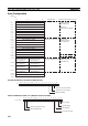
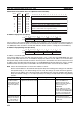
Socket Services Parameter Area 1 to 8 (Ethernet Unit to CPU Unit)
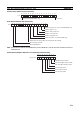
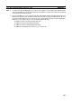
IP Address Display Area (CS Series)
The set values of the Local IP Address Switches (rotary switches 1 to 8) on the back of the Ethernet Unit are
read and stored here when the power is turned ON or the Ethernet Unit is restarted. If an incorrect address is
set, 0000 (Hex) will be stored here and the ERC indicator will flash. (Refer to Setting the Local IP Address.)
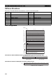
IP Address Display/Setting Area (CJ Series)
IP address: 12.34.56.78 (Hex)
If the local IP address in the CPU Bus Unit System Setup is set to a value other than 00.00.00.00, this area
(words m+98 and m+99) will act as an IP Address Display Area and the local IP address set in the CPU Bus
Unit System Setup will be read and stored here when the power is turned ON or the Unit restarted. If the local
IP address in the CPU Bus Unit System Setup is set to 00.00.00.00 (the default setting), this value is read by
the Ethernet Unit when the power is turned ON or the Unit restarted and is used as the local IP address.
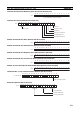
Note Choose the method used to set the local IP address as follows:
Set the local IP address in the CPU Bus Unit System Setup when making other settings in the CPU Bus
Unit System Setup (i.e., the default settings are not used). The settings are made with CX-Programmer.
Set the local IP address in the allocated words in the DM Area when using the CPU Bus Unit System
Setup at its default settings (i.e., for simple operation). The setting is usually made with a Programming
Console.
Offset Socket
No. 1
Socket
No. 8
Response code
15 14 13 12 11 10 9 8 7 6 5 4 3 2 1
0
...
+9
UDP/TCP socket number (1 to 8)
+0
m+18
m+88
...
Local UDP/TCP port number (0000 to FFFF Hex)+1 m+19 m+89
Remote IP address (00000000 to FFFFFFFF Hex)+2 m+20
m+21
m+90
m+91
Remote UDP/TCP port number (0000 to FFFF Hex)+4 m+22 m+92
...
Number of send/receive bytes (0000 to 07C0 Hex (1984))+5 m+23 m+93
Send/receive data address +6 m+24 m+94
(Same as FINS variable area designation method.)m+25 m+95
Timeout value (0000 to FFFF Hex)+8 m+26 m+96
m+27 m+97
...
1514131211109876543210
m+98
m+99
SW1 SW2 SW3 SW4
SW5 SW6 SW7 SW8
1514131211109876543210
m+98
m+99
(1) (2) (3) (4)
(5) (6) (7) (8)
Application Setting device Setting area Remarks
Simple operation (i.e.,
The CPU Unit Bus
System Setup is used
at its default settings.
Only the IP address is
set.)
Programming Console (CX-
Programmer can also be used.)
Allocated words in the DM Area The setting in the allocated
words in the DM Area is
enabled only when the IP
address in the CPU Unit Bus
System Setup is set to
00.00.00.00.
If the IP address in the CPU
Unit Bus System Setup is set to
a value other than 00.00.00.00,
this value is stored in the allo-
cated words in the DM Area.
Operation with the
CPU Unit Bus System
Setup set as desired
(i.e., The default set-
tings are not used.)
CX-Programmer CPU Unit Bus System Setup The IP address set in the CPU
Unit Bus System Setup is
stored in the allocated words in
the DM Area.