
Ethernet Units Operation Manual


28
Unit Components Section 3-3
Refer to 3-7 Creating an I/O Table.
8. For simple operation where the IP address only (and no other System Set-
up settings) is set, or for operation using the Programming Console only,
set the IP address in the allocated words in the DM Area using the CX-Pro-
grammer or Programming Console. (This method is mainly used when set-
ting the IP address in the allocated words in the DM Area using the
Programming Console only. When using this method, be sure to set the lo-
cal IP address value in the CPU Bus Unit System Setup to 00.00.00.00
(default). If a different value is set, the IP address set in the allocated words
in the DM Area will be overwritten with this value.)
Refer to 4-4 DM Area Allocations.
For operation with the System Setup set as desired, set the IP address in
the CPU Bus Unit System Setup with the CX-Programmer. This method is
used when setting the local IP address with the CX-Programmer. Any set
value other than 00.00.00.00 will be enabled as the local IP address.)
Refer to 4-2 CPU Bus Unit System Setup.
9. Create the routing tables using the CX-Net. (This step is required only if
FINS communications are used, or if CMND(490) is used by a PC with mul-
tiple Communications Units mounted to it.)
Refer to 3-8 Creating Routing Tables.
10. Make the settings in the System Setup using the CX-Programmer. (Create
the IP address table and IP router table.)
Refer to 3-9 System Setup, 3-10 Creating an IP Address Table, and 3-11
Creating an IP Router Table.
This step is required only in the following cases:
• When using a method other than automatic generation for IP address
conversion. (Address conversion method, IP address table.)
• When using the mail notification function.
• When setting a subnet mask.
• When setting an FTP login name and password.
• When Ethernet is configured in multiple segments. (IP router table)
• When Ethernet 4.28 is used (broadcast settings)
• When the UDP port number for FINS is changed to something other
than the default setting (9600).
11. Check communications. (Use PING command and an internode test.)
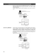
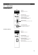
3-3 Unit Components
This section explains the Ethernet Unit’s components, settings, and LED indi-
cators. For details regarding the settings, refer to the individual explanations
later in this section.