
Controller Link Units Operation Manual

77
Wiring Section 3-3
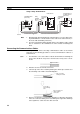
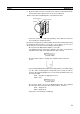
Remove the covers from the tips of the cables’ ST connectors if there are
covers protecting the ST connectors.
Note To replace the Optical Connector Cover, just reverse the steps shown
in the diagram above.
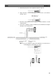
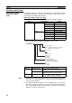
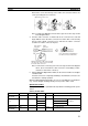
4. Turn the cable connector so that the tab in the connector faces left and
aligns with the slot in the Unit’s connector. Insert the cable connector fully
into the Unit’s optical connector. Press and turn the cable’s connector
clockwise to lock the connector in place.
Note To remove the connector, just reverse the steps shown in the diagram
above. (Press and turn the cable connector’s metal fitting counter-
clockwise to unlock the connector.)
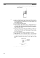
5. After installing the Optical Fiber Cable, fix the tension member of the Opti-
cal Fiber Cable.
Insert the connectors completely and always check that the connectors are
locked before starting operation.
When installing Optical Fiber Cables, be sure to stay within the specifications
(e.g., tensile strength, bending, lateral pressure) for the cables used.
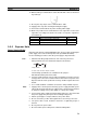
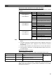
Optical Fiber Cables
Use Optical Fiber Cables (Graded Index: GI) with the following optical specifi-
cations.
50/125
µm AGF Cable
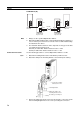
Optical Connector Cover
Pull off the cover.
Rotate the cover 90°
counterclockwise.
Slot
Cable
connector
Unit's optical
connector
Tab
Press and turn the metal fitting on
the cable connector until it locks.
Align the tab in the cable connector with
the slot in the Unit's connector and fully
insert the cable connector.
Item Minimum Standard Maximum Unit Conditions
Numerical Aper-
ture (N.A.)
--- 0.21 --- --- Theoretical value
Transmission
loss
--- --- 3.0 Lf dB 0.5 km ≤ Lf λ = 0.8 µm
T
a
= 25°C
3.0 Lf + 0.2 0.2 km ≤ Lf < 0.5 km
3.0 Lf + 0.4 Lf < 0.2 km
Connection loss --- --- 1.0 λ = 0.8 µm, one location
Transmission
bandwidth
500 --- --- MHz⋅km λ = 0.85 µm (LD)