
Controller Link Units Operation Manual


78
Constructing Networks with Repeater Units Section 3-4
Note L
f
is fiber length in km, T
a
is ambient temperature, and λ is the peak wave-
length of the test light source.
62.5/125
µm AGF Cable
Note L
f
is fiber length in km, T
a
is ambient temperature, and λ is the peak wave-
length of the test light source.
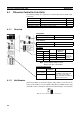
Connectors
ST Connector
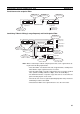
3-4 Constructing Networks with Repeater Units
Repeater Units can be used to construct flexible networks such as those
shown below.
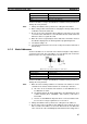
Note 1. Repeater Units must be supplied with 24-V DC power.
2. Wire-to-Optical Repeater Units (CS1W-RPT02 and CS1W-RPT03) are
used to convert a section of a wired network to optical fiber. Two Units are
always used as a single set.
Wire-to-Optical Repeater Units cannot be connected to Optical Ring/Opti-
cal Controller Link Units or Support Boards. If these types of Controller
Link Units or Support Boards are connected by mistake, communications
errors will occur throughout the network.
3. Repeater Units have a baud rate switch and a terminating resistance
switch. The same baud rate must be set for all nodes on the network.
In addition, the terminating resistance switch of Units (Controller Link
Item Minimum Standard Maximum Unit Conditions
Numerical Aper-
ture (N.A.)
--- 0.28 --- --- Theoretical value
Transmission
loss
--- --- 3.5 Lf dB 0.5 km ≤ Lf λ = 0.8 µm
T
a
= 25°C
3.5 Lf + 0.2 0.2 km ≤ Lf < 0.5 km
3.5 Lf + 0.4 Lf < 0.2 km
Connection loss --- --- 1.0 λ = 0.8 µm, one location
Transmission
bandwidth
200 --- MHz⋅km λ = 0.85 µm (LD)
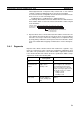
T-Branch Wiring
CS1W-RPT01
Repeater Unit
500 m max.
(at 2 Mbit/s)
500 m max.
(at 2 Mbit/s)
CS1W-RPT01
Repeater Unit
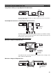
Long-distance Wiring
CS1W-RPT01
Repeater Unit
62-node Configuration
31 nodes max.
31 nodes max.
CS1W-RPT02/03
Repeater Unit
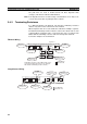
Partial Conversion to Optical Cable
Wire cable Wire cable
CS1W-RPT02/03
Repeater Unit
Optical cable