
Controller Link Units Operation Manual


86
CS-series Controller Link Units Section 4-1
4-1 CS-series Controller Link Units
The following settings are required for a Controller Link Unit used with a CS-
series PLC.
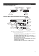
4-1-1 Overview
Unit Number
Node Address
Baud Rate
Note Factory default setting is in bold.
Always leave pins 3 and 4 OFF.
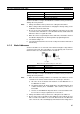
Terminating Resistance
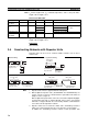
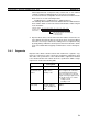
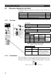
4-1-2 Unit Number
Set the unit number for each Unit using the rotary switches on the front of the
Unit. The unit number is used to identify a CPU Bus Unit within the PLC. Any
unit number can be set between 0 and F in hexadecimal (00 to 15 in decimal)
.
Item Switch Page
Unit number Unit number setting switch 86
Node address Node address switches 87
Baud rate Baud rate, pins 1 and 2 88
Terminating resistance Terminating resistance switch 89
CLK21-V1
Setting range Nodes
01 to F (default is 0) All nodes in the Network
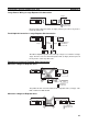
Setting range Nodes
01 to 32 (default is 01) All nodes in the Network
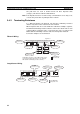
Pins Baud rate Maximum
transmission
distance
Nodes
Pin 1 Pin 2
OFF OFF 2 Mbps 500 m Set same
rate for all
nodes in the
Network.
ON OFF 1 Mbps 800 m
OFF ON 500 Kbps 1 km
ON ON Cannot be set.
Front switch Terminating
resistance
Nodes
OFF
(factory default)
Not connected All nodes in the Network
Turn ON the terminating resis-
tance at the nodes at both
ends of the Network and turn it
OFF at all other nodes.
ON Connected
Note: The factory default settings are shown above.