
Controller Link Units Operation Manual

97
CVM1 and CV-series Controller Link Units Section 4-4
4-4 CVM1 and CV-series Controller Link Units
The following settings are required for a Controller Link Unit when used with a
CVM1 or CV-series PLC.
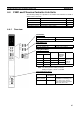
4-4-1 Overview
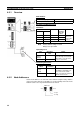
Unit Number
Node Addresses
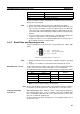
Setting Baud Rates
Note The factory default setting is in bold.
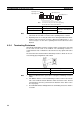
Always keep pins 3 and 4 set to OFF.
Terminating Resistance
Item Switch Page
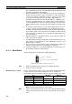
Unit number Unit number switch 98
Node address Node address switch 98
Baud rate Baud rate switch, pins 1 and 2 99
Terminating resistance Terminating resistance switch 99
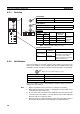
ON
CLK21
X10
1
X10
0
SW1
BD H
BD L
SHLD
RUN
ERC
M/A
LNK
TER SW
1
2
3
4
BAUD
RATE
BAUD RATE
00
INS
SD
M/A
LNK
RD
X10
0
NODE
NO.
X10
1
UNIT
NO.
X10
1
RSV
00
BIT2 BIT1 RATE
RSV
OFF OFF 2MBP
OFF ON 1MBP
ON OFF 500KBP
NODE
NO.
X10
1
X10
0
1
2
3
4
RSV
BAUD
RATE
0
ON
3214
X10
0
UNIT
NO.
X10
1
RSV
0
0
1
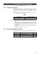
Setting range Nodes
00 to 15 (default is 00) All nodes in the Network
Setting range Nodes
01 to 32 (default is 01) All nodes in the Network
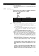
Switch Baud rate Maximum
transmis-
sion dis-
tance
Nodes
Pin 1 Pin 2
OFF OFF 2 Mbps 500 m Set same
rate for all
nodes in
Network.
ON OFF 1 Mbps 800 m
OFF ON 500 Kbps 1 km
ON ON Do not set.
Bottom switch Terminating
resistance
Nodes
OFF
(factory default)
Not connected All the nodes
Turn ON the terminating resis-
tance at the nodes at both
ends of the Network and turn it
OFF at all other nodes.
ON Connected