
Controller Link Units Operation Manual

141
Setting Data Links Section 5-2
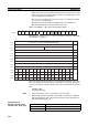
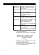
(Area start word − 1) + (Total number of send and receive words of
master node *)
≤ 6143 (when using the IR or CIO Area)
199 (when using LR Area)
32767 (when using DM or EM Area)
* Total number of send and receive words in master node =
Number of common send words in master node +
Number of individual send words in master node
× Number of slave
nodes participating in data links +
Number of send words in slave node
× Number of slave nodes partic-
ipating in data links
6. If a node that does not actually exist (e.g., a node that is scheduled to be
added in the future) is registered as a node that will participate in the data
links, a data link area for that node will be allocated in the master node, and
the send/receive area will be refreshed with “0” data.
7. Automatic data link creation with 1:N allocation can only be performed with
CS1W-CLK21-V1, CJ1W-CLK21-V1, 3G8F7-CLK21-V1 Controller Link
Units. If any other model is used, the LNK LED will flash and it will not be
possible to participate in the automatic creation with 1:N allocation.
8. If automatic data link creation with 1:N allocation is to be set up using CX-
Net operations in the CX-Programmer, use CX-Programmer Version 3.2 or
higher. Setup cannot be performed using CX-Programmer Version 3.2 or
lower.
9. The startup node (the node that sets the above DM parameter and starts
the data link) can be set at either a master node or a slave node.
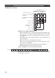
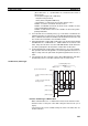
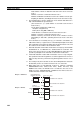
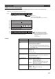
1:N Allocation, Chain Type
Features of Chain Type 1:N Allocation
• Data communications are 1:1 between the master node and slave nodes.
• All slave nodes receive part of the data sent by the master node. (1a in
figure).
• The master node receives all data sent by the slaves. The data sizes are
fixed for all nodes.
1a
1b
4
1a
2
2
3
2
1a
3
1a
3
4
1b
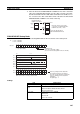
(4) Participating nodes
Master node Slave nodes
(1) Area and start word
(2) No. of master common send
words
(3) No. of receive and send
words per node
(Same as (3))
(Same as (3))
(Same as (3))