
Controller Link Units Operation Manual

147
Setting Data Links Section 5-2
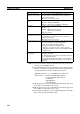
CVM1 or CV-series Startup Node
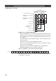
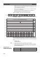
Set the following DM Parameter Area of the PLC of the startup node.
Settings
Data link mode
Set to 01 for automatic setting.
(00 is for manual setting. Other values are invalid.)
Number of send words per node of area 1 (BCD)
Rightmost 4 digits of data link start word of area 2 (BCD)
Leftmost digit of data link start word
of area 2 (BCD)
First data link status word (BCD)
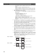
Word N
0: Always 0.
– : Other settings
15 14 13 12 11 10 9 8 765 4 3 2 10
15 8 7
0
15 14 13 12 11 10 9 8 7 6 5 4 3 2 10
1615141312111098765432
1
N+1
N+2
N+3
N+4
N+5
N+6
N+8
32 31 30 29 28 27 26 25 24 23 22 21 20 19 18 17
N+9
––
00000000 000
–
N+7
Area 2 type
Number of send words per node of area 2 (BCD)
Area 1 data link start word (BCD)
Area 1 type
N: DM 2000 + 100 × (Unit number of Controller Link Unit)
BCD: Set the value as binary-coded decimal.
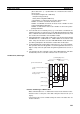
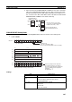
Nodes to participate in the data links
The numbers indicate node numbers.
The value assigned indicates whether the
node is to participate in the data links.
Participate: 1
Not participate: 0
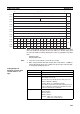
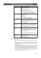
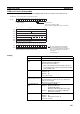
Item Setting range
Data link mode Specify automatic (01).
Area 1 data link start
word
Set the word address in BCD.
CIO Area: CIO 0000 to CIO 2555
LR Area: LR 000 to LR 199 (*)
*: When a word between LR 000 and LR 199 is speci-
fied, the data link area will be allocated between CIO
1000 and CIO 1199.
Area 1 type Set the area for area 1 in BCD.
CIO Area: 80
LR Area: 86
Area 1 not used: 00
Send size (number of
words) for node of area 1
Set the number of words in BCD between 0 and 1,000.
The total number of send words of area 1 and area 2
must not exceed 1,000.
When area 1 is not used, set to 0.
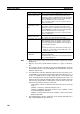
Area 2 data link start
word
Set the word address in BCD.
DM Area: DM 0000 to DM 8191
(CV500/CVM1-CPU01)
DM 0000 to DM 24575 (Other CPU Units)
EM Area: Banks 00 to 07, EM 0000 to EM 32765
(EM must be installed)
Area 2 type Set the area for area 2 in BCD.
DM Area: 82
EM Area: Banks 00 to 07: 90 to 97
Area 2 not used: 00