
Controller Link Units Operation Manual


160
Checking Data Link Status Section 5-4
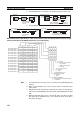
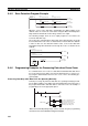
The data link status storage area is set as follows:
Note a) N: Unit number
b) Only status for nodes 1 to 6 are saved.
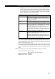
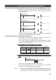
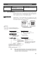
Data Link Status Storage Format (CS/CJ Series Only)
The setting for the data link status storage format when using CS- or CJ-
series PLCs is shown below. The setting is made using the software switch in
bit 7 of the DM Parameters Area. The address of the software switch is as fol-
lows:
DM 30000 + 100 x unit number
The user setting and automatic setting for the data link status storage format
are the same.
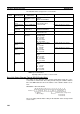
Data link
mode
PLC and
operating level
First data link
status word
Setting range Default status
Automatic CS/CJ-series PLC Specify in
DM 30000 + 100 ×
N + 7
Either 8, 16, or 31 words
between
CIO 001 and CIO 6640
CIO 1500 + 25 × N + 7 to 22
C200HX/HG/HE
Level 0
Specify in DM 6407 16 words between
IR 001 and IR 220 or
IR 300 to IR 496
IR 239 to IR 241 (See note b.)
C200HX/HG/HE
Level 1
Specify in DM 6427 IR 243 to IR 245 (See note b.)
CVM1 or CV-
series PLC
Specify in DM 2000
+ 100 × N + 7
16 words between
CIO 000 and CIO 2540
CIO 1500 + 25 × N + 7 to 22
CQM1H-series
PLC
Specify in DM 6407 16 words between
IR 000 and IR 232
IR 91 to IR 93 (See note b.)
Manual CS/CJ-series PLC Specify in the data
link tables
Either 8, 16, or 31 words in the
following ranges
CIO: 1 to 6640
LR: 0 to 184
DM: 0 to 32752
EM: 0 to 32752
CIO 1500 + 25 × N + 7 to 22
C200HX/HG/HE
Level 0
16 words in the following
ranges
IR: 1 to 220
IR: 300 496
LR: 0 to 48
DM: 0 to 5984
EM: 0 to 6128
IR 239 to IR 241 (See note b.)
C200HX/HG/HE
Level 1
IR 243 to IR 245 (See note b.)
CVM1 or CV-
series PLC
16 words in the following
ranges
CIO: 1 to 2540
LR: 0 to 184
DM: 0 to 24560
EM: 0 to 32750
CIO 1500 + 25 × N + 7 to 22
CQM1H-series
PLC
16 words in the following
ranges
IR: 1 to 232
LR: 0 to 48
DM: 0 to 5984
EM: 0 to 6128
IR 91 to IR 93 (See note b.)
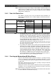
Address N
0: Always 0
-: Other settings
Data link status storage format
0: 8-bit format
1: 4-bit format
-