
Controller Link Units Operation Manual


258
Data Link I/O Response Time Section 8-3
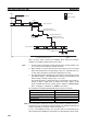
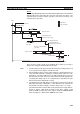
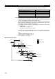
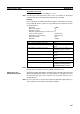
There are three points shown in the diagram above where processing is
delayed, increasing the data link I/O response time.
1,2,3... 1. The input arrives in the PLC just after I/O refreshing, causing a delay of up
to one cycle before the input is read into the PLC.
2. Data exchange occurs just after the PLC at node #1 passes the token that
makes it the polling node, causing a delay of up to one communications cy-
cle time before the data is transferred in data link processing.
3. The data transferred in data link processing arrives at the PLC at node #7
after data exchange, so the data will not be read into the PLC until the next
data exchange, causing a delay of up to 1 to 2 cycle.
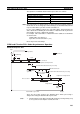
The maximum number of words that can be exchanged in a single data ex-
change is approx. 7,800 words for CS/CJ-series PLCs, approx. 3,700
words for CVM1 and CV-series PLCs, approx. 4,000 for C200HX/HG/HE
PLCs, and approx. 1,200 words for CQM1H-series PLCs.
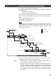
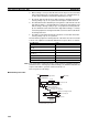
The equation for maximum data link I/O response time is as follows:
Note If the total number of data link words is greater than the maximum number of
words that can be exchanged per data exchange, the maximum data link I/O
response time will be cycle time of PLC at node #7
× 3.
In case of the CQM1H, however, the cycle time will be incremented by the
value obtained from dividing the total number of data link words by the maxi-
Input device
Program
Program
Input
Input ON delay
1 cycle
Output
Output device
Output ON
delay
1 cycle
Communications
cycle time
Data link transmission
Controller Link Unit
transmission processing
PLC at node #7
(1)
I/O refresh
Data exchange
Controller Link Unit
transmission processing
PLC at node #1
Data link I/O response time
X
X
(2)
(3)
X
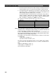
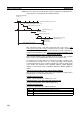
Input ON delay 1.5 ms
Cycle time of PLC at node #1 × 215 ms × 2
Communications cycle time × 39.9 ms × 3
PLC cycle time at node #7 × 2 (See note.) 8 ms × 2 (See note.)
Output ON delay 15 ms
Total (data link I/O response time) 92.2 ms