
Controller Link Units Operation Manual

16
Specifications and Configurations Section 1-2
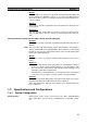
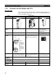
1-2-4 Controller Link Unit Models and PLCs
Wired System
There are five Controller Link Units: One for CVM1 and CV-series PLCs, one
each for CS-series and CJ-series PLCs, one for the C200HX/HG/HE PLC,
and one for CQM1H-series PLCs.
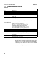
Item Specifications
Model CS1W-CLK21-V1 CJ1W-CLK21-V1 C200HW-CLK21
External appear-
ance
Installation
devices
None required. None required. C200HW-COM01/04 Commu-
nications Board and
C200HW-CE001/002/012 Bus
Connection Unit
PLC CS-series PLCs CJ-series PLCs C200HX/HG/HE PLCs
(Except C200HE-CPU11(-Z))
Max No. of Units
per PLC
8 maximum for unit Ver. 1.2 or
later and 4 maximum for pre-Ver.
1.2 Units.
8 maximum for unit Ver. 1.2 or
later and 4 maximum for pre-Ver.
1.2 Units on CPU or Expansion
Rack
2 maximum
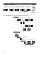
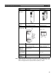
Installation site Install onto a CPU Backplane or
CS-series Expansion Backplane
(Classified as a CPU Bus Unit.)
Install onto a CPU Rack or
Expansion Rack (Classified as a
CPU Bus Unit.)
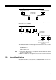
Install onto a CPU Back-
plane. (Classified as a Special
I/O Unit for communications.)
Storage location
for network
parameters
CPU Bus Unit Area (in the CPU Unit parameter area) Controller Link Unit
Storage location
for routing tables
CPU Unit parameter area DM 6450 to DM 6499 in CPU
Unit
Weight 400 g 110 g 400 g
Current con-
sumption
330 mA 350 mA 300 mA
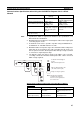
RUN
C
L
K
2
1
ERC
INS
ERH
M/A
LNK
RD
TER
SD
BAUD
RATE
1
2
ON
SW1
ON
TER SW
BD H
BD L
SHLD
0
1
2
3
4
5
6
7
8
9
A
B
C
D
E
F
0
1
2
3
4
5
6
7
8
9
0
1
2
3
4
5
6
7
8
9
U
N
IT
No.
NODE
No.
x10
1
x10
0
ON
1
2
CPU Backplane
Expansion
Backplane
2/3/5/8/10 slots
3/5/8/10 slots
CPU
Unit
Of these
slots,
installation is
possible in up
to 8 slots (unit
Ver. 1.2 or
later).
Installation in
up to 4 slots
is possible for
pre-Ver. 1.2
Units.
CPU Backplane
2 max.
CPU
Unit