
Controller Link Units Operation Manual

74
Wiring Section 3-3
Communications Cables
Optical Bus or Optical
Ring System (H-PCF
Cable)
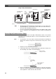
The following devices are required for the Optical Bus or Optical Ring (H-PCF)
Controller Link Network. The cable and connectors are the same as those
used for Optical SYSMAC LINK Networks.
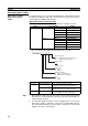
Optical Fiber Cables (Indoor Use Only)
Use the following Optical Fiber Cables (Hard Plastic-clad Fiber: H-PCF).
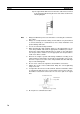
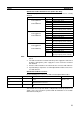
Note The Optical Fiber Cable model numbers are as follows.
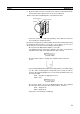
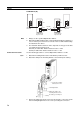
Note 1. Either full-lock or half-lock connectors can be used in a Controller Link Net-
work, but we recommend full-lock connectors to prevent accidental discon-
nections during operation.
2. The maximum distance between nodes is slightly shorter for connectors
with crimp-cut cables compared to connectors assembled with adhesive.
Also, the maximum distance is reduced due to extension loss when Inline
Adapters are used to extend cables.
Name Specifications Model
H-PCF cables Black 10 m S3200-HCCB101
50 m S3200-HCCB501
100 m S3200-HCCB102
500 m S3200-HCCB502
1,000 m S3200-HCCB103
Orange 10 m S3200-HCCO101
50 m S3200-HCCO501
100 m S3200-HCCO102
500 m S3200-HCCO502
1,000 m S3200-HCCO103
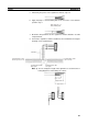
Name Model Specifications
Connector S3200-COCF2071 Use to connect a cable to a node.
(Full-lock connector for crimp-cut cable.)
S3200-COCF2571 Use to connect a cable to a node.
(Half-lock connector for crimp-cut cable.)
Inline Adapter S3200-COIAT2000 Use to connect or extend cables.
(Use one adapter for each connection.)
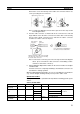
S3200-H@@@@@@@
Tensioner option
None: Standard (with tension member)
N: Without tension member
Cable length
@@@
A B
(A/10) x 10
B
m
Cable color
B: Black
O: Orange
Cable specification
L: With power supply line
C: Without power supply line
Type
B: Cord
C: Cable