
Controller Link Units Operation Manual

178
Introduction Section 6-1
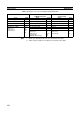
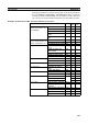
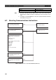
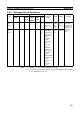
Note Specify the area code according to the following table.
Note 1. Words 0 to 2555 in the IR Area can send and receive data.
2. Timer/counters numbers 0 to 2047 can send and receive data.
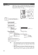
Destination node: CS/CJ-series PLC Destination node: C200HX/HG/HE or
CQM1H-series PLC
Destination node: CVM1 or
CV-series PLC
Area Code Area Code Area Code
CIO (IR, etc.) (See note 1.) 00 IR (Internal Relay) 00 CIO 00
TIM (Timer) (See note 2.) 03 LR (Link Relay) 06 CPU Bus Link 01
CNT (Counter) (See note 2.) 04 HR (Holding Relay) 07 Auxiliary 02
DM (DM Area) 05 AR (Auxiliary Relay) 08 Timer 03
EM (Expansion DM)
Banks 0 to 7
Banks 8 to 13
Current bank
10 to
17
A8 to
AC
18
TC (Timer/Counter) 03 Counter 04
DM (DM Area) 05 DM (DM Area) 05
EM (Expansion DM)
Banks 0 to 7
Banks 8 to 15
Current bank
(CQM1H: Bank 0 only)
10 to
17
28 to
2F
18
EM (Expansion DM)
Banks 0 to 7
Current bank
10 to
17
18