
Controller Link Units Operation Manual

184
Introduction Section 6-1
For details on commands for CS/CJ-series PLCs, refer to the CS/CJ-series
Programmable Controllers Instructions Reference Manual (W340). For details
on commands for CVM1 and CV-series PLCs, refer to the FINS Commands
Reference Manual (W227). For details on commands for C200HX/HG/HE
PLCs, refer to 6-6 Commands and Responses for C200HX/HG/HE and
CQM1H-series PLCs. For details on commands for Controller Link Units, refer
to 6-5 Commands and Responses for Controller Link Units.
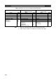
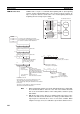
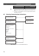
6-1-3 Send/Receive Data Areas
The data areas that can be used as operands in the SEND and RECV instruc-
tions depend on the PLC, as shown in the following tables. Be sure to set the
operands so that the end of the data area is not exceeded.
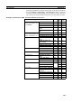
CS/CJ-series PLCs
Note 1. Writing is not possible to words A000 through A447 in the Auxiliary Area.
2. A maximum of thirteen banks can be used for Expansion DM. For details
on extended DM Area and the number of banks, refer to the operation
manual for the PLC model that is being used.
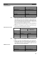
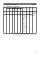
File Memory FILE NAME READ 2201 Yes Yes
SINGLE FILE READ 2202 Yes Yes
SINGLE FILE WRITE 2203 Yes Yes
MEMORY CARD FORMAT 2204 Yes Yes
FILE DELETE 2205 Yes Yes
VOLUME LABEL CREATE/
DELETE
2206 No Yes
FILE COPY 2207 Yes Yes
FILE NAME CHANGE 2208 Yes Yes
FILE DATA CHECK 2209 No Yes
MEMORY AREA FILE
TRANSFER
220A Yes Yes
PARAMETER AREA FILE
TRANSFER
220B Yes Yes
PROGRAM AREA FILE
TRANSFER
220C Yes Yes
Forced set/reset FORCED SET/RESET 2301 Yes Yes
FORCED SET/RESET
CANCEL
2302 Yes Yes
Type of command Code CS/
CJ
CVM1/
CV
Area Range
CIO (IR etc.) CIO 0000 to CIO 6143
Work Area (WR) W000 to W511
Holding Area HR000 to HR511
Auxiliary Area AR000 to AR959 (See note 1.)
Timer T0000 to T4095
Counter C0000 to C4095
DM Area DM00000 to DM32767
Extended DM Area EM00000 to EM32767 (See note 2.)