
Controller Link Units Operation Manual

244
Setting Routing Tables Section 7-4
7-4-8 Example Routing Table Settings
This section shows examples of routing table settings.
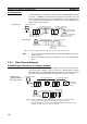
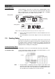
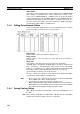
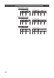
Example 1 The example below shows local network table settings when multiple CPU
Bus Units are mounted in a single CVM1 or CV-series PLC.
Do not register SYSMAC BUS/2 Master Units and BASIC Units in local net-
work tables because these Units do not connect to networks.
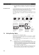
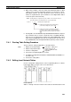
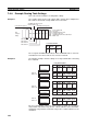
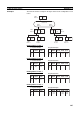
Example 2 The following example show the settings for a relay network table connecting
three networks.
On closer examination of the relay network table for PLC#, we see that the
relay network is B and the relay node is c when network A is the destination,
and that the relay network is B and the relay node is e when network C is the
destination.
CLK SNT RM BSC CPU PS
1
2
A
B
(d)
(c)
Unit number d
Unit number c
Unit number b
Unit number a
SYSMAC BUS/2 SystemController Link System
Network address A
PS: Power Supply Unit
CPU: CPU Unit
SNT: SYSMAC NET Link Unit
CLK: Controller Link Unit
RM: SYSMAC BUS/2 Remote I/O Maste
r
BSC: BASIC Unit
No.
Loc
Netwk
SIOU
unit #
Local Network Table
PLC
acting as
bridge
SYSMAC NET Link System
Network address B
CS1-series PCs
1
2
B
C
A
A
b
b
1
2
A
C
B
B
c
e
1 CBe
1 ABc
Relay Network Tables
No.
End
Netwk
Relay
PC ID Netwk Node
Relay
PC ID Netwk Node
Relay
PC ID Netwk Node
Relay
PC ID Netwk Node
Relay
PC ID Netwk Node
No.
End
Netwk
No.
End
Netwk
No.
End
Netwk
Network
address A
Network
address B
Network
address C
PLC 1
Node address a
PLC 2
Node address b
Node address c
PLC 3
Node address d
PLC 4
Node address e
Node address f
PLC 5
Node address g
1
2
A
B
C
C
f
f
No.
End
Netwk