
Controller Link Units Operation Manual

280
Troubleshooting Using Indicators Section 9-1
Node Cannot Participate
in Data Link
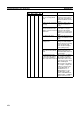
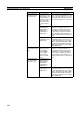
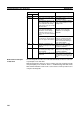
The following table describes the LNK and M/A indicators when a node can-
not participate in the data links.
Data link participation depends on the Controller Link Unit operating normally
and participating in the Network. Refer to Troubleshooting with RUN, ERC,
ERH and INS Indicators earlier in this section and check Unit operation before
using the following table.
Data Link Cannot be
Stopped
Stopping the data link depends on the Controller Link Unit operating normally
and participating in the Network. Read the above explanations before
attempting to stop operation.
Note Stop the data link from the node at which the LNK indicator is lit (indicating
active data links). Data links cannot be stopped from nodes which do not have
active data links.
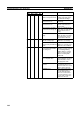
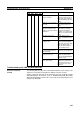
Troubleshooting of Other Errors
To configure a network that uses a node address higher than 32, all nodes
must be CS1W-CLK21-V1, CJ1W-CLK21-V1, or 3G8F7-CLK21-V1. The
Wired Network 62 Node Enable Bit in the DM Parameters Area must also be
turned ON (62 nodes max.) for all nodes. If the nodes are set differently, the
network will not be configured correctly. If the settings are incorrect, the follow-
ing problems will occur.
Indicators Probable cause Probable remedy
LNK M/A
Lit --- Data link operating normally. ---
Flashing Lit When manual setting is used,
there is an error in the data link
table.
Refer to 5-2-2 Manual Setting
and remake the data link table.
Flashing Not lit When automatic setting is
used, the data link parameters
at the startup node are incor-
rect for the local node (the
data link area is out of range
for the local node.)
Refer to 5-2-4 Automatic Set-
ting, reset the parameters for
the startup node DM Area so
that the local node can partici-
pate in the data link, and then
restart the data link.
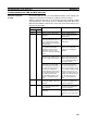
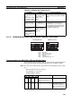
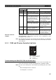
When automatic setting is
used, the local node is not set
to participate in the data link at
the startup node.
Stop the data link, reset the
parameters for the startup
node DM Area so that the local
node can participate in the
data link, and then restart the
data link.
Automatic setting is used with
1:N allocations, but the device
does not support this function.
Use a Controller Link Unit that
supports automatic data link
creation with 1:N allocations.
Refer to Automatic Setting on
page 129 for details.
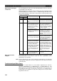
When a number exceeding
12,000 was set for the data
link send and receive words or
the same memory area was
set for Area 1 and Area 2
using a CS/CJ-series Control-
ler Link Unit with unit version
1.2 or later that was then
replaced with a CS/CJ-series
pre-Ver. 1.2 Controller Link
Unit.
The number of data link send
and receive words cannot
exceed 12,000 and the same
memory area cannot be set for
Area 1 and Area 2 when using
a CS/CJ-series pre-Ver. 1.2
Controller Link Unit. Either use
a CS/CJ-series Controller Link
Unit with unit version 1.2 or
later or reset the data link
tables.
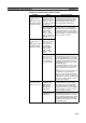
Not lit Lit When manual setting is used,
there are no data link tables
set for the local node.
Set data link tables for the
local node.