
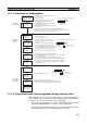
Controller Link Units Operation Manual


328
Handling Precautions Section 9-6
2. Detach the communications cables and the Bus Connection Unit attached
to the Controller Link Unit to be replaced and remove the Unit.
3. Mount the new Controller Link Unit in the PLC and connect the communi-
cations cables and the Bus Connection Unit. (Refer to SECTION 3.)
4. Set the node address, baud rate, operating level (front DIP switch,
C200HX/HG/HE only) and the terminating resistance for the new Unit to
the same settings as the previous Unit. (Refer to SECTION 4.)
5. Turn ON only those PLC for which Units were replaced.
6. Set the following software switches on the new Controller Link Unit using
the Programming Device.
• Polled node/ polling nodes: ON (polled node)
• EEPROM Clear But: ON (EEPROM Clear)
7. Turn off the power again to PLCs for which the Controller Link Unit has
been changed.
8. If the CPU Unit DIP switch pin 5 of the PLC for which the Controller Link
Unit has been replaced is ON (automatic transmission), set to OFF (no au-
tomatic transmission.)
9. Turn off all nodes in the Controller Link Network.
10. If the Controller Link Support Software can be operated, use it to read the
network parameters and make sure the Network is operating normally.
11. If the data links are not activated automatically, activate the data link from
the data link startup node.
12. If the Controller Link Support Software can be operated, use it to check
that the data links are operating normally by monitoring the data link status.
13. Return the software switches set in step 6. in the new Controller Link Unit
to the following settings using the Programming Device.
• Polled node/polling node: OFF (polling node)
• EEPROM Clear Bit: OFF (Do not clear EEPROM)
Check the above if the Controller Link Support Software can be used.
14. If DIP switch pin 5 on the CPU Unit was switched from ON to OFF in set
8., turn the PLC OFF once, return the DIP switch to ON, and turn the power
ON again.
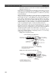
CS/CJ-series, CVM1, and CV-series Controller Link Units
Note CS/CJ-series, CVM1, and CV-series Controller Link Unit data is stored in the
EEPROM of the CPU Unit. For this reason even if the Controller Link Unit is
replaced, on the hardware settings must be made to return all settings to their
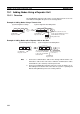
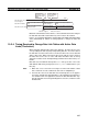
Operating level 0
DM 6400
Operating level 1
DM 6420
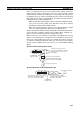
– : Other settings
EEPROM Clear Bit 0: Do not clear EEPROM
1: Clear EEPROM
Polled node/polling node 0: Polling node
1: Polled node
DM 6400
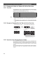
C200HX/HG/HE
CQM1H Series
–: Other settings
EEPROM Clear Bit 0: Do not clear EEPROM
1: Clear EEPROM
Polled node/polling node 0: Polling node
1: Polled node
Operating level 0
DM 6400
Operating level 1
DM 6420
DM 6400
C200HX/HG/HE
CQM1H Series