INDUSTRIAL DATA COMMUNICATIONS USER GUIDE DDAA1000/SRM Discrete/Analog Wireless Multiplexer It is essential that all instructions contained in the User Guide are followed precisely to ensure proper operation of equipment.
Product User Guide FCC Notification This device complies with part 15 of the FCC rules. Operation is subject to the following conditions: 1) 2) This device may not cause harmful interference and This device must accept any interference received, including interference that may cause undesired operation. The device must be operated as supplied by Data-Linc Group.
DDAA1000/SRM User Guide Table of Contents Page Introduction Discrete Operation Analog Operation Changing System or Radio Configurations ○ ○ ○ ○ ○ ○ ○ ○ ○ ○ ○ ○ ○ ○ ○ ○ ○ ○ ○ ○ Technical Support Return Material Authorization Contact Information ○ ○ ○ ○ ○ ○ ○ ○ Appendix A Enclosure Dimensions Appendix B System Configuration ○ ○ ○ ○ ○ ○ ○ ○ ○ ○ ○ ○ ○ ○ ○ ○ ○ ○ ○ ○ ○ ○ ○ ○ ○ ○ ○ ○ ○ ○ ○ ○ ○ ○ ○ ○ ○ ○ ○ ○ ○ ○ ○ ○ ○ ○ ○ ○ ○ ○ ○ ○ Mo
DDAA1000/SRM User Guide 2 DATA-LINC GROUP PN 161-09981-002C rev 8/04
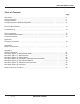
DDAA1000/SRM User Guide Introduction The DDAA1000/SRM and DD1000/SRM are discrete/analog signal multiplexers. They are designed to provide increased communication distance where wire lengths are too long or not possible. In general, these units behave as if they replace a set of wires between the two or more locations. These units are normally factory configured and eliminate the necessity of having to preset the system configurations. The units are ready for installation into the system upon receipt.
DDAA1000/SRM User Guide Table 1: LED Description CD Carrier Detect LED. When the units have established an RF Link this LED will be on solid. Tx Transmit LED. Will flash when the unit is sendng data to the receiving unit. Rx Receive LED. Flashes when receiving data being sent by transmitting unit. Pw r Power LED. Flashes on solid when unit has power applied. Status The status LED will be off when communication is working properly.
DDAA1000/SRM User Guide Discrete Operation Requirements 1. The outputs of the units cannot directly drive a relay. The digital outputs are open collector current sinking to the common ground. An external power supply must be used to provide DC power to any relays. 2. The maximum voltage on the relay driver outputs is 24 VDC. 3. Ensure that the pull up voltage is sufficient for your relay. i.e. a 12 VDC relay needs 12 VDC, a 24 VDC relay needs 24 VDC. 4.
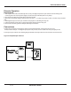
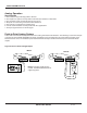
DDAA1000/SRM User Guide Point-to-Point Discrete Operation The following illustrates an example of a point-to-point discrete system. The “Contact Closure Input” may be as simple as a bare wire or be connected to an output of an I/O module. This is an example of turning a lamp at the Master unit by closing a contact at the Remote unit using a discrete output. Point-to-point discrete operations are bi-directional. An input on the Remote will activate same numbered output on the Master.
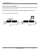
DDAA1000/SRM User Guide Point-to-Multipoint Discrete Operation A multipoint system will involve two or more remote locations, which may be transmitting contact input information, providing discrete outputs or both. The following is an example of a multipoint configuration. In this example, the Master is transmitting a contact closure input to both Remotes. Note that input #1 on the Master will trigger the same numbered output on all Remote units at the same time.
DDAA1000/SRM User Guide Analog Operation Specifications 1. This unit does not provide loop power to devices. 2. The outputs can operate on loops with a maximum total resistance of 300 ohms. 3. The resolution of this unit is 8 bits with accuracy of 2%. 4. All inputs use a common ground connection labeled “G”. 5. This system is not designed to replace PLCs. 6. It is not recommended to use this product with PLC applications. 7. The input signal must be a 4-20 mA signal.
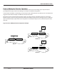
DDAA1000/SRM User Guide Figure 7: Connection of a flow meter to the DDAA1000/SRM unit Master or Remote Pwr 4-20mA Output 4-20mA Input G 1 5 6 7 8 G 1 2 3 4 5 6 7 8 +- Loop Power 12 -24 VDC Supply B 2 3 4 A 4-20mA Out In from Sensor Flow Meter PN 161-09981-002C rev 8/04 DATA-LINC GROUP 9
DDAA1000/SRM User Guide Point-to-Multipoint Analog System Unlike the discrete versions, the system must be configured for where specific inputs and outputs are directed. Each unit is normally factory configured and designed to interface with the specific system. Alterations to this configuration are possible using an accessory cable and jumpers and software provided by Data-Linc Group. Reconfiguring the units requires the removal of the cover and uses a custom serial data cable connected to a computer.
DDAA1000/SRM User Guide Point-to-Multipoint Analog Operation A system is to be built where one analog input exist at one remote and one at another. The maximum possibility of master outputs is eight, so this is a valid configuration. Remote 0 being the first remote in the Master’s poll list will be assigned Master output one. Remote 1 being next in the poll list will be Master output two.
DDAA1000/SRM User Guide Changing System or Radio Configurations To access the system or radio setups the user must remove all connectors from the DDAA1000/SRM or DD1000/SRM, then remove the cover and change the jumpers at location P1 and P2, and add a serial data cable (SRM6200E-SLC), supplied by Data-Linc Group, to connector P3. These jumper settings must be returned to the RUN/RF settings after reconfiguring the system or the radio or the units will not operate. See layout drawing.
DDAA1000/SRM User Guide Technical Specifications Channels DD1000/SRM has 8 discrete inputs and 8 discrete outputs. DDAA1000/SRM has 8 discrete inputs, 8 discrete outputs, 8 analog inputs and 8 analog outputs. Channel Specifications Analog: 2% accuracy or better with a maximum output load of 300 ohms. Discrete: Open collector outputs which can handle up to 24V and can sink up to 100 mA for controlling relay coil. Temperature 32o to 140 o F (0 o to 60 o C) Power 10.5 - 18 VDC. Maximum current draw is 660 mA.
DDAA1000/SRM User Guide Troubleshooting I have the units setup on a bench for testing, but the Master’s status LED keeps flashing or is solid and I do not have a carrier. When shipped, the units are setup for a maximum transmit power of 1 watt. If there are only a couple feet of separation between them, the supplied whip antenna may need to be removed. Note that this will not damage the unit. The units are installed in the field, but I have a flashing or solid LED on the status and no carrier.
DDAA1000/SRM User Guide Technical Support Data-Linc Group maintains a fully trained staff of service personnel who are capable of providing complete product assistance. They can provide you with technical, application and troubleshooting, spare parts and warranty assistance. Our technical staff is based in Bellevue, Washington USA and may be reached at (425) 882-2206 or e-mail support@data-linc.
DDAA1000/SRM User Guide Appendix A Enclosure Dimensions TOP 6.85 5.655 8 7 6 5 4 3 2 8 1 G 7 6 5 4 3 2 1 G CONTACT CLOSURE OUTPUT CONTACT CLOSURE INPUT STATUS CD Tx Rx 4.065 3.935 4.80 approx POWER DATA-LINC GROUP 3.18 (425) 882-2206 DDAA1000/SRM/M PWR 4 - 20mA INPUT G 1 2 3 4 5 4 - 20mA OUTPUT 6 7 8 G 1 2 3 4 5 6 7 8 Ø 0.19 6.35 SIDE 1.725 16 1.65 1.
DDAA1000/SRM User Guide Appendix B Figure 10: PCB Layout DDAA1000 - DD1000 Configuration The system configuration parameters are stored in an EEprom memory. This memory can only be changed by the onboard microprocessor using serial commands via port P3. The easiest method is to use the Data-Linc Group program provided with the master unit, to be run on a PC. If the program is missing contact Data-Linc Group Technical Support. A DDAA1000/DD1000 system is normally factory pre-configured.
DDAA1000/SRM User Guide If you have the Data-Linc Group PC program DDAAEEprom.exe it is designed to run in Windows. Load the program DDAAEEprom.exe into your PC. Start the program. When the system layout window appears fill in the following information: 1. Select Model DDAA or DD1000 with mouse click. 2. The PCs Comm (serial port) number 1 or 2 with a mouse click. 3. The serial Baud rate that the DDAA1000/DD1000 uses to talk to the radio module. This is not the connection speed to the computer.
DDAA1000/SRM User Guide The number of analog values received from a remote is the same as the number of analog inputs sent to a remote. If a DDAA remote unit has no analog input/outputs assigned it must have an address(1 to 7) higher than any remote using the analog input. i.e. All remotes using 4-20mA input/outputs must be assigned addresses lower than any digital only remotes. After filling in the chart click on the “Make an EEprom” button and follow the prompting instructions on the screen.
DDAA1000/SRM User Guide 6. The unit will now ask for the number of ADs (analog inputs) on each Remote. ‘#ADsSlv0’. The question is repeated for each Remote unit. ‘#ADsSlv1’.etc. Any units that have no (zero) active analog channels must be put after any remotes that do have analog channels. Enter the number of analogs channels for each Remote. 7. The display now asks for the number of analog inputs at the Master unit.
DDAA1000/SRM User Guide Appendix C Radio Configuration The radio module in the DDAA1000/DD1000 can be set to suit your particular application. All adjustments are done through the built-in setup program, with a user interface that eliminates the need for setup diskettes or custom software. The radio modules used in the DDAA1000/DD1000 are factory pre-configured.
DDAA1000/SRM User Guide When the setup program the main menu will appear on the screen. The main menu also displays the radios unique ID number and firmware version. The user selects the parameter group by pressing a single key. The next level menu is then displayed. Select the parameters you want to change with a single keystroke. Now you can enter the parameter or data value. To return to the previous menu press the ‘ESC’ escape key. When done making changes, press the ‘ESC’ key at least 3 times.
DDAA1000/SRM User Guide Main Menu Option (0): Set Operation Mode When item (0) is selected, the Operation Mode Menu appears as shown in figure 12. The Operation Mode option is used to designate the method in which the particular DDAA1000/SRM will be used. The DDAA1000/SRM operates in a master to remote configuration; therefore, any radio modems that are intended to operate together must be set up as such.
DDAA1000/SRM User Guide (4) Point-to-Point Remote/Repeater Option 4 allows you to designate the radio modem to act as either a remote or a repeater, depending upon the instructions received from the master for the specific communications session. When a radio modem is placed in an ideal location, this setting offers the flexibility of using that radio modem as an end point in the communications link (remote) or to extend the link to a point further (repeater).
DDAA1000/SRM User Guide Main Menu Option (1): Set Baud Rate When option (1) is selected you will be able to change the radio modem’s RS-232 baud rate. This is the communication rate between the radio modem and the instrument to which it is connected. It is important to note that this is independent of the baud rate for the other radio modem(s) in the communication loop. For example, DDAA1000/SRMs may be used in an application to send data from remote process instrumentation to an engineer’s computer.
DDAA1000/SRM User Guide Main Menu Option (2): Edit Call Book If the DDAA1000/DD1000 system is only two (2) units, one Master and one Remote, then either Point-to-Point or Multipoint modes can be used. If the system has more than one Remote, then Point-to-Multipoint mode must be used. Use of the Call Book for multi-point systems is explained later in this chapter. The Call Book is an innovative feature in the DDAA1000/SRM that offers both security and flexibility in use.
DDAA1000/SRM User Guide Entering or Modifying Numbers in the Call Book Entering or modifying call book numbers in the Call Book is a straightforward process. When in the Call Book menu, select the entry number (0 – 9) you wish to edit. You will be prompted for the new number (formatting is automatic, you do not need to enter the dash). Once the number is entered (unless it is 000-0000) you will be asked for the call number of the first repeater to be used.
DDAA1000/SRM User Guide Main Menu Option (3): Edit Radio Transmission Characteristics When option (3) is selected in the main menu the screen in figure 14 appears, which allows the user to modify the radio transmission characteristics of the radio modems. As stated in the warning, these parameters are for the experienced user who has a good understanding of the principles of radio data transmission. They should be changed only after consulting this user guide.
DDAA1000/SRM User Guide Table 4: Minimum Packet Size Settings (bytes) Setting Min Packet Siz e RF Data Rate = 2 Setting Min Packet Siz e RF Data Rate = 3 0 16 0 8 1 21 1 12 2 26 2 16 3 32 3 20 4 37 4 24 5 42 5 28 6 48 6 32 7 53 7 36 8 58 8 40 9 64 9 44 Table 5: Maximum Packet Size Settings where RF Data Rate=3 Minimum Setting Maximum Setting 0 1 2 3 4 5 6 7 8 9 0 8 24 40 56 72 88 104 120 136 152 1 12 28 44 60 76 92 108 124 140 156
DDAA1000/SRM User Guide Table 6: Maximum Packet Size Settings where RF Data Rate=2 Minimum Setting Maximum Setting 0 1 2 3 4 5 6 7 8 9 0 15 36 58 79 100 121 143 164 185 206 1 20 42 63 84 105 127 148 169 190 212 2 26 47 68 90 111 132 153 175 196 217 3 31 52 74 95 116 137 159 180 201 222 4 36 58 79 100 121 143 164 185 206 228 5 42 63 84 105 127 148 169 190 212 233 6 47 68 90 111 132 153 175 196 217 238 7 52 74 95 116
DDAA1000/SRM User Guide (5) RF Xmit Power The DDAA1000/SRM offers users the ability to modify the Transmission Power of the radio modem. There are 10 power settings available (1-10) which are roughly linear. Therefore a setting of 10 is full power (or 1 Watt) and 1 is 10% power (or 100 mw).
DDAA1000/SRM User Guide (9) Lowpower Mode For DDAA1000/DD1000 use the user should not change this parameter. Do not enable the low power mode. (A) High Noise Use the menu to indicate if the modem will be operated in an environment with a high degree of radio noise and interference. With a setting of 1, the rejection of interference is improved, at the cost of reduced range and/or throughput. (B) MCU speed Use this menu to set the speed of the MCU (processor) in the modem.
DDAA1000/SRM User Guide Main Menu Option (4): Show Radio Statistics Option (4) in the main menu allows the user to view data transmission statistics, which have been gathered by the Transceiver during the most recent session. Statistics are gathered during each data link and are reset when the next link begins. Ideally, noise levels should be below 30, and the difference between the average signal level and average noise level should be 15 or more.
DDAA1000/SRM User Guide Number of Disconnects If, during the course of performing a link test, the link between the master and the remote is broken, and the radios lose carrier detect, the occurrence is recorded in the Number of Disconnects value. The value indicates the total number of disconnects that have occurred from the time the link test started until the radio was put into config mode. Under normal operating conditions, the number of disconnects should be 0.
DDAA1000/SRM User Guide Main Menu Option (5): Edit Multi-Point Parameters Figure 15: Multi-Point Parameters Shown below are example settings. Please refer to supplied configuration sheets for your modem’s configuration. In a multi-point network, it is critical to know how many radio modems are being used as repeaters. Any radio modem that is used as a repeater essentially becomes a master to the remotes and other repeaters to which it is communicating.
DDAA1000/SRM User Guide Another parameter in a multi-point network is (4) DTR Connect. When set at (1), the remote will connect to the master if it is free when the DTR line goes high on the 9-pin RS232 connector. In setting (2), the radio modem will accumulate data in its buffer and transmit in a burst when the buffer is full. This mode is valuable when a network has many low data rate devices and it is desirable to increase overall network capacity.
DDAA1000/SRM User Guide SubNet ID The DDAA1000/SRM series modems offer a SubNet ID system for use in multi-point networks using Network ID. This feature allows the users to dictate what path a given repeater or remote will use to achieve a link to the network master. For example, if a remote modem in a given network has line of sight to the network master and one or more repeaters, but only one repeater is close to that remote, SubNet ID can be used to link that master with the proper repeater only.
DDAA1000/SRM User Guide To back out of the process and not enable the password, hit escape. To set a password, type in exactly 4 characters. At any point in the process you can cancel by hitting the escape key. Once the 4 characters have been entered, you will be prompted with “ to accept, to quit”. At this point, if you wish to accept the password entered and enable the feature, press the enter key.
DDAA1000/SRM User Guide DDAA1000/SRM and DD1000/SRM Placement Locations Placement of your DDAA1000/DD1000 is likely to have a significant impact on its performance. In general, the rule of thumb with the DDAA1000/DD1000 is that the higher the placement of the antenna, the better the communication. In practice you should also place the radio itself away from computers, telephones, answering machines, and other similar equipment.