OMRON ETHERNET Direct DAServer User’s Guide Ver 1.x Rev 1.4 DR 170 14 KLINKMANN AUTOMATION P.O. Box 38 FIN-00371 Helsinki Finland tel. int. + 358 9 5404940 fax int. + 358 9 5413541 www.klinkmann.
Klinkmann Automation Omron Ethernet DAServer i Contents Before You Begin .......................................................................................................... 2 About This User Guide............................................................................................... 2 Introduction.................................................................................................................... 2 Overview .....................................................................
Klinkmann Automation Omron Ethernet DAServer ii Component Environments ......................................................................................... 67 Before You Begin About This User Guide This user’s guide describes the user interface and functions of the KLINKMANN OMRON Ethernet Direct DAServer. It also provides you with the step-by-step procedures on how to configure and use the OMRON Ethernet Direct DAServer after it is installed.
Klinkmann Automation Omron Ethernet DAServer 2 CHAPTER 1 Introduction This chapter provides you with an overview of the KLINKMANN OMRON Ethernet Direct DAServer, including the application- and bus-level communications protocols, item naming conventions and DAServer features.
Klinkmann Automation Omron Ethernet DAServer 3 Microsoft Windows program capable of acting as a DDE, SuiteLink ™ or OPC client that can also coexist with FactorySuite ™ 2000 and greater. Communication Protocols The OMRON Ethernet Direct DAServer communicates with clients and PLCs using the following different communications protocols: • Application communications protocols such as OPC, DDE and SuiteLink to communicate with clients located on either local or remote nodes.
Klinkmann Automation Omron Ethernet DAServer 4 FastDDE FastDDE provides a means of packing many proprietary Wonderware Dynamic Data Exchange messages into a single Microsoft DDE message. This packing improves efficiency and performance by reducing the total number of DDE transactions required between a client and a server. Although Wonderware's FastDDE has extended the usefulness of DDE for our industry, this extension is being pushed to its performance constraints in distributed environments.
Klinkmann Automation Omron Ethernet DAServer 5 To access an OPC item, the OPC client needs to connect to the DAServer (either inprocess or out-of-process) and create an OPC group defining the data-acquisition properties for the collection of items to be added. OPC groups can be either public or private. Public OPC groups are shared across multiple clients, whereas private OPC groups are local to a single client.
Klinkmann Automation Omron Ethernet DAServer 6 • topic name: Meaningful names are configured in the DAServer to identify specific devices. These names are then used as the topic names in all conversations with that device. For example, OmronPLC. Topic name maps to a device group defined in the DAServer. Note: You can define multiple device-group (topic) names for the same device (PLC) to poll different points at different rates. • item name: A specific data element within the specified topic.
Klinkmann Automation Omron Ethernet DAServer 7 /2003 installation package, Commandline Installation”) can be obtained from Klinkmann software downloads page: http://www.klinkmann.com/automation/klinkmann-software-products/communicationsoftware-products-prices/ and it is located in “Additional and service software” section. 2. The $SYS$Licensed system item value with OMRON Ethernet Direct DAServer is not relevant. Omron Ethernet DAServer Ver 1.x User Manual Rev 1.
Klinkmann Automation Omron Ethernet DAServer 8 CHAPTER 2 Before starting the OMRON Ethernet DAServer This chapter contains instructions how to configure OMRON PLCs to be accessible by Omron Ethernet DAServer in OMRON Ethernet FA network. Configuration example deals with local network. If data are to be accessed from remote networks then Relay Network Tables must be additionally configured in the PLC.
Klinkmann Automation Omron Ethernet DAServer 9 Configuration software tool, appropriate (and recommended) for all OMRON controllers is OMRON CX-Programmer Windows Programing Software (see “OMRON CX-Programmer Users Manual”) . Ethernet Unit Configuration Example for CS1 PLC Connect the computer to the PLC CPU unit with Host Link Cable. Install the CXProgrammer software. Set IP Address table. Start CX-Programmer (from Start menu: Start/.../CXProgrammer/CX-Programmer).
Klinkmann Automation Omron Ethernet DAServer 10 When CX-Programmer establishes communication with PLC, select "Operating Mode" (from PLC's menu) and set "Program" mode.
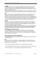
Klinkmann Automation Omron Ethernet DAServer 11 When IO Table is received, display the slot list under Main Rack (press "+" button in the "PLC IO Table - NewPLC1" dialog box). Select "Ethernet Unit(ET)(0)" and press the mouse right button. The Ethernet Unit menu appears: Omron Ethernet DAServer Ver 1.x User Manual Rev 1.
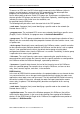
Klinkmann Automation Omron Ethernet DAServer 12 Click "Unit Setup". The "Ethernet Unit CPU Bus Unit" dialog box appears: Omron Ethernet DAServer Ver 1.x User Manual Rev 1.
Klinkmann Automation Omron Ethernet DAServer 13 Enter Address Conversion type, FINS UDP port number and Sub-net Mask. Edit the IP Address Table: the computer where Omron Ethernet DAServer is running must be added to the IP Address Table. To add it, press "Insert" button. The "Insert Router's IP Address" dialog box appears: Enter the Node Number (in example 55) matching to the last octet in IP Address of computer where Omron Ethernet DAServer is running.
Klinkmann Automation Omron Ethernet DAServer 14 To complete the configuration: from the "Ethernet Unit CPU Bus Unit" (or from the "PLC IO Table - NewPLC1") dialog box select "Options" and click "Transfer to PLC". Example program for sending “unsolicited” data from PLC The PLC example program presented in Plcprg.
Klinkmann Automation Omron Ethernet DAServer 15 by-time poll area D500…D509 and time-by-time gets unsolicited command assigning to items D500…D509 values of PLCs D10…D19 area. Even if corresponding Controller is configured to be processed in slave mode – at communication start-up DAServer process several general data reading commands, accessing toggle effect. If your application does not need toggling effect – configure SEND(090) instruction so, that source area matches to destination area.
Klinkmann Automation Omron Ethernet DAServer Omron Ethernet DAServer Ver 1.x User Manual Rev 1.
Klinkmann Automation Omron Ethernet DAServer 17 CHAPTER 3 Configuration Once the KLINKMANN Omron Ethernet DAServer has been installed, a small amount of configuration is required. This configuration is performed using the DAServer Manager hosted in the System Management Console after it is started through the Programs menu of the Windows Start button.
Klinkmann Automation Omron Ethernet DAServer 18 4. From the System Management Console, find the Omron Ethernet DAServer in the DAServer Manager tree, the location in which it is installed. • Under the Local branch node, the name of the DAServer is Archestra.DASOmronEth.1. • See the DAServer Manager documentation for general information about working in this snap-in environment. 5. The new Omron Ethernet DAServer must now be configured.
Klinkmann Automation Omron Ethernet DAServer 19 DAServer Manager, click the Help topics on the SMC Help menu. Both the MMC Help and the DAServer Manager Help are displayed. An Adobe Acrobat version of the DAServer Manager documentation (DAServerManager.pdf) is also available in the CDROM directory\User Docs\English. Note: For better understand how to read and write data to the different OMRON controllers, please refer to the chapter Before starting the Omron Ethernet DAServer.
Klinkmann Automation Omron Ethernet DAServer 20 Note: See the DAServer Manager documentation for general information about working in this snap-in environment. 7. Before the DAServer is started, you must first build the device hierarchy to establish communications to each of the controllers. Important! For step-by-step procedures on how to build the device hierarchy, please see the following section, "DASOmronEth Hierarchy in the DAServer Manager.
Klinkmann Automation Omron Ethernet DAServer 21 • To activate the DAServer, right-click on ArchestrA.DASOmronEth.1 and select Activate Server from the shortcut menu. Note: To run the Omron Ethernet DAServer as a service, right-click on the DAServer name and select Configure As Service from the shortcut menu. You can configure it as an auto service or manual service.
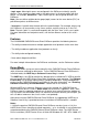
Klinkmann Automation Omron Ethernet DAServer 22 Enter/modify SOCKET parameters. Host Name (IP Addr.) Enter the Computer’s Internet Address (IP Address) if it has more than one. If there is only one Internet Address for computer then you can use default address 0.0.0.0. Port Number Enter the UDP Port Number used for communication with OMRON Controllers.
Klinkmann Automation Omron Ethernet DAServer 23 This configuration view has 15 parameters (configuration requires proven network information, it can not be validated by the DAServer): • Enter Controller’s Network Address - to each network in the OMRON system can be assigned an unique network address between 0 and 127. When communicating with a node on another (remote) network, the entered value must be consistent with the network address (non-zero) assigned in the routing tables.
Klinkmann Automation Omron Ethernet DAServer 24 C/CPM2x series offers 5 options (C200HS, C200H, C1000H, C2000H, CPM2x) and CQM1 series offers 1 option (CQM1). • Enter Reply Timeout field - the amount of time (in seconds) the PLC will be given to reply to commands from the DAServer. Note: The default value of 3 seconds should be sufficient for most configurations. • Enter the value of the Access Delay (in milliseconds).
Klinkmann Automation Omron Ethernet DAServer 25 Check or uncheck the Slave Mode check box to select the principles how to obtain data from corresponding controller. If Slave Mode is not checked (Master mode) – DAServer polls data from controller all the time. In Slave Mode (if checked) DAServer requests data from Controller only once – at communication start-up and then only waits for unsolicited messages from controller (writing to controller is still supported).
Klinkmann Automation Omron Ethernet DAServer 26 Note: Default Watchdog state is “non-active”, i.e. Watchdog Time Interval is equal to zero. Note: In order to use the DAServer, you must activate it. See the DAServer Manager documentation for information about how to activate and deactivate the DAServer.
Klinkmann Automation Omron Ethernet DAServer 27 Here the “Customer ID” is “computer-dependent” string generated by DASOmronEth and “Product ID” is DASOmronEth product code and version. Write down both the “Customer ID” and “Product ID”or Copy/Paste to e-mail when ordering the DASOmronEth. 3) After purchasing the DASOmronEth, you will get the software license key –16character alphanumeric string.
Klinkmann Automation Omron Ethernet DAServer 28 Note: When you select another part of the DAServer tree hierarchy, you are prompted to save the modifications to the configuration set. To create or add device groups 1. To create or add device groups, right-click in the Device Groups box. 2. Select the Add command from the shortcut menu. • When you add a new device group, enter a unique name.
Klinkmann Automation Omron Ethernet DAServer 29 The Device Group parameters dialog can be used to configure preferred Read mode and Write optimization mode. If Memory Area Read is checked (default setting), then Server uses Memory Area Read FINS commands and maximum (Read FINS Message Maximum Size – 14) / 2 consecutive words can be read from this Controller by one read command.
Klinkmann Automation Omron Ethernet DAServer 30 changed in the following sequence: DM0, 500R, DM1, 502R, DM2, ... then DAServer creates a separate write message for each new write value. If Any Msg Multiple Write option is checked, DAServer tries to include the new write value into any of previously created messages ignoring the sequence of data changing in the client application.
Klinkmann Automation Omron Ethernet DAServer 31 Since you more than likely want very fast response, the temptation is to set the Update Interval to a value close to 0 seconds. However, if every point is polled at this rate, the entire system will suffer due to slow response time. Therefore, you should compromise, and set the Update Interval to a more reasonable value.
Klinkmann Automation Omron Ethernet DAServer 32 Each device item definition should contain a unique name for the PLC associated with it. Device Item Definitions The Device Items dialog box, which is displayed by clicking the Device Items tab in the CV500 Parameters configuration view, is used to add, clear all, rename, delete, import and export device items. The Device Items dialog box has the following two columns: • Name: This column defines the alias names to actual PLC items.
Klinkmann Automation Omron Ethernet DAServer 33 1. In the Item Reference column, double-click on the area in the same horizontal line as the selected device item. 2. Type in the actual PLC item name in the frame that appears. 3. Click anywhere in the dialog box or press the Enter key to have the change take effect. To rename a device item from the list 1. Right-click on the device item to be renamed. 2. Select the Rename command from the shortcut menu and enter the new device item name. 3.
Klinkmann Automation Omron Ethernet DAServer 34 The Omron Ethernet DAServer is hot-configurable. The following hot-configuration functionality is incorporated in Omron Ethernet DAServer: • Modifying Global Configuration parameters. • Adding, deleting, or modifying device nodes (without affecting any other device nodes, excluding the children of the modified device nodes). • Adding, deleting, or modifying device groups.
Klinkmann Automation Omron Ethernet DAServer 35 CHAPTER 4 Item Names The Omron Ethernet DAServer supports item/point names consistent with the point naming conventions used by OMRON PLCs and programming software. The Server supports almost all memory areas of the following OMRON PLC types: CS1, CJ1, C200HX, C200HG, C200HE, CV-series, C-series, CPM2x and CQM1.
Klinkmann Automation Omron Ethernet DAServer 36 contains 8000 hex. In this case item name DM100 or DM100U would be displayed in client as 32768. Signed quantities may be read from the same channel by appending the suffix 'S' (or 's') to the item name. So, item name DM100S would be displayed in client as -32768. BCD Format To read/write data using BCD format - append the suffix ‘B’ (or ‘b’) to the item name, e.g. DM100B.
Klinkmann Automation Omron Ethernet DAServer High-order Byte Both Bytes 37 Only the high-order byte (MSB - most significant 8-bits) of each word is used for read. To use this format, append the suffix 'D' to the item name. Both bytes of each word are used for read/write. To use this format, append the suffix 'C' to the item name. Note: All bytes in the specified memory range will be used. If the string is shorter than the range of memory specified, it will be padded with '\0'.
Klinkmann Automation Omron Ethernet DAServer 38 CS1/CJ1 PLCs The following table lists the supported item names for the CS1/CJ1 PLCs: Memory Area Prefix Tag Range Value Rang Type e CIO Area 0, 1 Discrete CIO0:00...CIO6143:15 CIO (Bit status) or 0.00...6143.15 CIO Area Integer CIO0... CIO6143 (*) CIO (Word contents) or 0...6143 Work Area W0:00... W511:15 0, 1 Discrete W (Bit status) Work Area Integer W0... W511 (*) W (Word contents) Holding Area H0:00...
Klinkmann Automation Omron Ethernet DAServer 39 Item/point names, corresponding to CIO Area, may be without prefix. (*) Value range for unsigned integer is from 0 to 65535 (item/point name with suffix "U" ("u") or without suffix), for signed integers from –32768 to 32767 (item/point name with suffix "S" ("s")) and for 16-bit BCD is from 0 to 9999. The value range for long or 32-bit integer is from -2147483648 to 2147483647 and for 32-bit BCD is from 0 to 99999999.
Klinkmann Automation Omron Ethernet DAServer 40 C200HX/C200HG/C200HE PLCs The following table lists the supported item names for the C200HX, C200HG and C200HE PLCs.
Klinkmann Automation Omron Ethernet DAServer 41 (****) Read only The following examples show the correct format for item names for C200HX, C200HG, C200HE PLCs and SYSMAC Board: IR2:01 257 LR62.10 DM21 - Internal Relay Area (Bit status), word address 2, bit number 1.
Klinkmann Automation Omron Ethernet DAServer Step Timer Present Value Expansion area Current bank (Bit status) Expansion area Current bank (Word contents) Expansion area A (Bit status) Expansion area A (Word contents) Expansion area B (Bit status) Expansion area B (Word contents) Expansion area C (Bit status) Expansion area C (Word contents) Expansion area D (Bit status) Expansion area D (Word contents) Expansion area E (Bit status) Expansion area E (Word contents) Expansion area F (Bit status) Expansion a
Klinkmann Automation Omron Ethernet DAServer 43 Item/point names, corresponding to Input/Output register area CIO, may be without prefix. (*) Value range for unsigned integer is from 0 to 65535 (item/point name with suffix "U" ("u") or without suffix), for signed integers from 32768 to 32767 (item/point name with suffix "S" ("s")) and for 16-bit BCD is from 0 to 9999. The value range for 32-bit integer is from -2147483648 to 2147483647 and for 32-bit BCD is from 0 to 99999999.
Klinkmann Automation Omron Ethernet DAServer 44 C/CPM2x PLCs The following table lists the supported item names for the C-series PLCs: Memory Area Prefix CIO area (Bit status) CIO area (Word contents) Latching Relay area (Bit status) Latching Relay area (Word contents) Holding Relay area (Bit status) Holding Relay area (Word contents) Auxiliary Relay area (Bit status) Auxiliary Relay area (Word contents) Completion flags for Timers/Counters(***) Present Values for Timers/Counters Data Memory area (Bit s
Klinkmann Automation Omron Ethernet DAServer 45 Memory Area Prefix IR & SR areas (Bit status)(***) IR & SR areas (Word contents) (***) Latching Relay area (Bit status) Latching Relay area (Word contents) Holding Relay area (Bit status) Holding Relay area (Word contents) Auxiliary Relay area (Bit status) Auxiliary Relay area (Word contents) Completion flags for Timers/Counters(**) Present Values for Timers/Counters Data Memory area (Bit status) (****) Data Memory area (Word contents) (****) IR Tag Type
Klinkmann Automation Omron Ethernet DAServer 46 CQM1 PLCs The following table lists the supported item names for the CQM1 PLCs: Memory Area Prefix IR & SR area (Bit status) IR & SR area (Word contents) LR area (Bit status) LR area (Word contents) HR area (Bit status) HR area (Word contents) AR area (Bit status) AR area (Word contents) Completion flags for Timers/Counters(***) Present Values for Timers/Counters DM area (Bit status) DM area (Word contents) EM area (Bit status) EM area (Word contents) IR
Klinkmann Automation Omron Ethernet DAServer 102 LR62.10 DM21 - 47 IR Output area (Word contents), word address 102 LR area (Bit status), word address 62, bit number 10 DM area (Word contents), word address 21 DAServer Standard System Items System Items provide you with easy access to the DAServer status and diagnostics information. They are treated just like ordinary items with respect to the client. However, in most cases these items are not directly acquired via the communications layer.
Klinkmann Automation Omron Ethernet DAServer 48 DAServer Global System Item The following system item refers to specific information regarding a global condition of the DAServer. System Item Name Type/ Access Rights $SYS$Licensed Boolean/ Read Description Binary status indication of the existence of a valid license for the DAServer.
Klinkmann Automation Omron Ethernet DAServer practical application, OPC clients should reference $SYS$Status at any hierarchy levels other than the root. Detailed error code of the communications state to the device. The device group (OPC access path/topic) does not affect the value. $SYS$ErrorCode Longint/ Read $SYS$ErrorText String/ Read Detailed error string of the communications state of the device. The device group (OPC access path/topic) does not affect the value.
Klinkmann Automation Omron Ethernet DAServer 50 DAServer Device-Group-Specific System Items The following system items refer to specific information regarding device groups that have been configured in the DAServer. System Item Name $SYS$UpdateInterval Type/ Access Rights DWord/ ReadWrite Description Used to access the currently set update interval. It is the current update interval of the device group in milliseconds. A client can poke new values into this item.
Klinkmann Automation Omron Ethernet DAServer $SYS$ReadComplete Integer/ ReadWrite $SYS$ItemCount DWord/ Read $SYS$ActiveItemCoun t DWord/ Read $SYS$ErrorCount DWord/ Read $SYS$PollNow Boolean/ ReadWrite or a -1 to test a client reaction on write errors). If the value of this item is zero, it cannot be poked. Used to access the state of initial reads on all items in the corresponding device group. The value is 1 if all active items in a device group have been read at least once.
Klinkmann Automation Omron Ethernet DAServer 52 device groups with a zero update interval (manual protocol triggering). Generic OPC Syntax DAServer serves as a container for the OPC Groups, which provide the mechanism for containing and logically organizing OPC items. Within each OPC Group, an OPCcompliant client can register OPC items, which represent connections to data sources in the field device. In other words, all access to OPC items is maintained through the OPC Group.
Klinkmann Automation Omron Ethernet DAServer 53 CHAPTER 5 Troubleshooting This chapter describes the troubleshooting tools you can use to deal with the Omron Ethernet DAServer problems you may encounter. The DAServer Manager provides access to diagnostics and other statistical data, and the Log Viewer provides access to event messages logged during the operation of a DAServer. Also, your client (for example, InTouch) can monitor connectivity with the PLC through the $SYS$Status item.
Klinkmann Automation Omron Ethernet DAServer 54 YourOPCAccessPath is the assembly of hierarchy node names leading to a specific controller device. $SYS$Status is the discrete item used to monitor the status of connectivity with the controller device. Note: In the case of a PLC disconnect, the DAServer will retry three times before entering into slow poll mode. In the case of reply time-out, the DAServer will go into slow poll mode immediately.
Klinkmann Automation Omron Ethernet DAServer 55 In this example, each time the value of changes in the PLC, the DAServer will automatically send the new value to the cell containing the formula in Excel. Note: Refer to the Microsoft Excel manual for complete details on entering Remote Reference formulas for cells. Writing Values to the DAServer from Excel Values may be written to the DAServer from Microsoft Excel by creating an Excel macro that uses the POKE command.
Klinkmann Automation Omron Ethernet DAServer 56 Error Messages and Codes Generic DAServer error messages and Omron Ethernet-DAServer-specific messages are supported. Use the Log Flag data to customize the messages logged to the Log Viewer. See the Log Viewer online documentation for more information about using log flags. To troubleshoot DAServer problems, use the following error messages together with the DAServer Manager Diagnostics root data.
Klinkmann Automation Omron Ethernet DAServer 57 < Socket_ ControllerName>: Invalid Watchdog Address must be valid Item name. Do not process Watchdog. Failed creation of Watchdog message. Watchdog message is not processed until solving the problems. Invalid Watchdog Address configured. HASP key not found! DAServer does not find the valid HASP key installed DAServer does not find valid HASP key installed. Server will run 1 hour in demo mode.
Klinkmann Automation Omron Ethernet DAServer Item () was not created: max allowed message's length is not sufficient. of response message) exceeds max read message length, configured for Controller object. : CreatePokeMessage, cannot get Item's () value, error = : Write message for Item (
Klinkmann Automation Omron Ethernet DAServer : Item () read illegal BCD value hex, returning 19999. : Item () read illegal BCD Long value hex, returning 199999999. 59 and writing back modified word value into PLC’s memory. Here the processing of first step failed. Data, received from PLC, cannot be converted into right BCD value. Assigned value 19999.
Klinkmann Automation Omron Ethernet DAServer 60 Server-Specific Error Codes There are following server-specific error codes, shown in the table, that augment those provided by the DAS Toolkit. Error code -10002 -10003 -10004 Logger Message PLC timeout No Eth. Socket created PLC Fatal Error(*) Log Flag DASProtFail DASProtFail DASProtFail Note: Error code can be monitored in client application as Item’s $SYS$ErrorCode value, correspondingly Logger Message can be monitored as Item’s $SYS$ErrorText value.
Klinkmann Automation Omron Ethernet DAServer 02: Remote node error 03: Communic. Controller error 61 number too large. number below the maximum node number. 03 Send error caused by lack of available space in PLC internal buffers. Reduce the traffic on the DASProtFail Ethernet Unit. Check user application. 05 Node number setting error. Make sure the node number is within specified range and that there are no duplicate node numbers. 06 Node number duplication error.
Klinkmann Automation Omron Ethernet DAServer 62 operation manual) 04 Node number setting error. Make sure the node number is within specified range and that there are no duplicate node numbers. DASProtFail 04: Not executable 01 An undefined command has been used, or short frame (4 bytes) is being used for FINS header frame. Check the command code and be sure code is supported by Unit to which command is sent.
Klinkmann Automation Omron Ethernet DAServer 22: Status error 23: Environmen t error 25: Unit error 63 UDP/TCP socket number was not within the proper range and 8. 01 An incorrect memory area or unavailable expansion mem. area has been used. Check the command’s DASProtFail memory area code. Check whether right controller type configured in DAServer. Check whether controller does has polled memory areas. 03 The first address is in inaccessible area.
Klinkmann Automation Omron Ethernet DAServer data transfer between the CPU unit and a CPU Bus Unit). 0A 64 issue the ERROR CLEAR command An error occured during Check the Units and CPU Bus Unit data cable connection and transfer. issue the ERROR CLEAR command DASProtFail Note: Refer to FINS Command’s manual if face FINS error code missed in table. (*) If face this type of error – contact Klinkmann Support (support@klinkmann.
Klinkmann Automation Omron Ethernet DAServer 65 CHAPTER 6 Reference Contents • DAServer Architecture • Component Environments DAServer Architecture Note: DAServers are supported on Microsoft Windows 2000 and Windows XP only. NetDDE protocol is not supported by DAServers. This DAServer is a collection of components that work in concert to provide communications access with hardware field devices.
Klinkmann Automation Omron Ethernet DAServer 66 Each physical part of a DAServer is comprised of a set of .exe and/or .dll modules. Wonderware provides the Plug-ins and the DAS Engine. The DAS Toolkit user creates the PLC Protocol Layer (DAServer-specific) modules. All three sets of modules are required for a fully functioning DAServer. Plug-ins Plug-ins provide a protocol-translation function for device integration clients.
Klinkmann Automation Omron Ethernet DAServer 67 The PLC Protocol Layer provides a protocol-translation function for specific hardware, such as OMRON FinsGateway; and it serves as an interface between the DAS Engine and the hardware. Component Environments Stand-alone DAServers have the following characteristics: • The DAS Engine is dynamically linked to the other DAServer components.
Klinkmann Automation Omron Ethernet DAServer 68 KLINKMANN AUTOMATION Omron Ethernet Direct DAServer Revision History Mar 2005 Dec 2005 Rev 1.0 Rev 1.1 Oct 2007 Rev 1.2 May 2009 Rev 1.3 Mar 2011 Rev 1.4 First Release “Computer Node” Address removed from CONTROLLER Object parameters configuration. “Gateway Count (GCT)” field added into CONTROLLER Object parameters configuration. Support for CS1/CJ1 Extended Memory bank 0 to bank C (in Hex), up to 13 banks, added.