
Home Security System User Manual

107
Cyclic Refresh Section 5-3
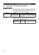
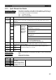
5-3-3 Cyclic Refresh Area Details
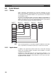
Coordinator Module
Cyclic Refresh Area
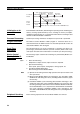
CIO 0100 to CIO 0109 in each Motion Control Module is allocated to ten
words between CIO 0100 to CIO 0139 in the Coordinator Module according to
the slot number for the Motion Control Module.
CM: Coordinator Module
MM: Motion Control Module
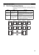
Motion Control
Module Cyclic
Refresh Areas
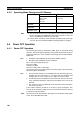
Motion Control Modules use CIO 0100 to CIO 0109, as shown in the following
table.
CM: Coordinator Module
MM Motion Control Module
Word
address
Bits Details
CIO 0100 to
CIO 0104
00 to
15
CM Output Refresh Area (CM to MM)
The data in this area is allocated to the MM Input Refresh Area (CM to MM) for Motion Control
Module #1.
CIO 0105 00 to
07
Reserved.
08 Refresh Area for
MM #1
CM Input
Refresh Area
(MM to CM)
The data in the
MM Output
Refresh Area
(MM to CM) for
MM #1 is allo-
cated here.
Reserved
09 Cycle time over warning
OFF: No error
ON: Cycle time exceeded 10 ms.
10 MM #1 non-fatal error (including FAL instructions)
OFF: No non-fatal error
ON: Non-fatal error
11 MM #1 fatal error (including FALS instructions)
OFF: No fatal error
ON: Fatal error
12 to
14
Reserved
15 MM #1 program status
OFF: Stopped (PROGRAM mode)
ON: Executing (RUN or MONITOR mode)
CIO 0106 to
CIO 0109
00 to
15
CM Input Refresh Area (MM to CM)
The data in the MM Output Refresh Area (MM to CM) for MM #1 is allocated to this area.
CIO 0110 to
CIO 0119
00 to
15
Refresh Area for
MM #2
Same as for MM #1.
These areas can be used as work bits by the Coordinator Module when no
Motion Control Modules are connected.
CIO 0120 to
CIO 0129
00 to
15
Refresh Area for
MM #3
CIO 0130 to
CIO 0139
00 to
15
Refresh Area for
MM #4
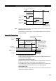
Word
address
Bits Details
CIO 0100 00 to 15 MM Input Refresh Area (CM
to this MM)
The data in the Coordinator
Module's CM Output Refresh
Area (CM to MM) is allocated
to this area.
General-purpose refresh data from CM to MM.
CIO 0101 00 to 15
CIO 0102 00 to 15
CIO 0103 00 to 15
CIO 0104 00 to 15