
Home Security System User Manual


152
Pulse Inputs Section 7-5
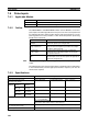
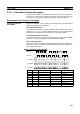
7-5-5 Latch Input Specifications
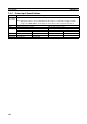
7-5-6 Applicable Instructions
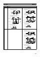
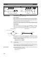
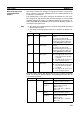
7-5-7 Internal Circuit Configurations
Pulse Inputs
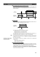
Phases A and B
Phase Z
Item Specification
Number of inputs 2
Input voltage 20.4 to 26.4 V
Input response ON response: 30 µs
OFF response: 200 µs
Instruction Control Description
(@)CTBL(882) Range comparison One range comparison executed.
Target value comparison table regis-
tration and starting comparison
Target value comparison table registered and comparison
started.
Target value comparison table regis-
tration
Target value comparison table registered.
(@)INI(880) Starting comparison Comparison started with previously registered target value com-
parison table.
Stopping comparison Target value comparison stopped.
Changing PV PV of high-speed counter changed.
Changing circular value Maximum circular value of high-speed counter changed.
(@)PRV(881) Reading high-speed counter PV PV of high-speed counter read.
Reading high-speed counter move-
ment or frequency
Movement or frequency of high-speed counter read.
Reading the latched high-speed
counter PV
Latched PV of high-speed counter read. (Reads the PV input to
the latch register when the latch signal was input.)
4.4 kΩ
Phase A and B
internal circuits
−
1
2
1 24-V input
2 Line-driver input
+
3.0 kΩ
Phase Z
internal circuit
−
1 24-V input
2 Line-driver input
1
+
2