
Home Security System User Manual


20
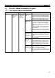
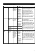
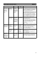
Function Tables Arranged by Purpose Section 1-7
Synchronizing 3
or more axes
Make control
cycle as short
as possible with
Modules syn-
chronized
Synchronizing
Motion Control
Modules only
Sync Mode,
Sync Cycle
Time
5-1 Synchronous Operation between Modules
Set Sync Mode to Sync and Sync Cycle Time to
between 0.1 and 10.0 ms.
If the Coordinator Module cycle varies or gets
too long after connecting the FQM1 to peripheral
devices, Motion Control Module operation can
be synchronized to have short control cycles for
Motion Control Modules only.
The Sync Cycle Time can be set to any value.
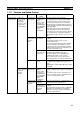
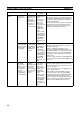
Synchronous
Data Link Bit
Area
Same as “Synchronous Data Link Bit Area,”
above.
Cycle Time
(Motion Control
Modules)
5-1 Synchronous Operation between Modules
The Coordinator Module's constant cycle time is
set as the FQM1 Sync Cycle Time (as above).
The I/O refresh interval for the Motion Control
Module in that Sync Cycle Time is made con-
stant and the I/O cycle with external interfaces is
also made constant.
Prohibit System
Interruption of
the Sync Mode
Same as “Prohibit System Interruption of the
Sync Mode” above.
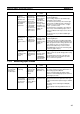
Control opera-
tion using pulse
and analog data
simultaneously
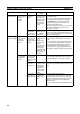
Synchronizing
Motion Control
Modules to
Coordinator
Module cycle or
synchronizing
between Motion
Control Mod-
ules only
Synchronous
Data Selection
5-4 Synchronous Data Refresh
Information for I/O from different Motion Control
Modules can be stored within Modules and a
control loop created.
Select the type of synchronous data.
• Ladder execution results
• High-speed counter PV
• Pulse output PV
• Analog input values
• Analog output values
• Built-in I/O inputs
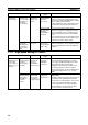
Fast control
loops
Changing to
Async Mode
Sync Mode 5-1 Synchronous Operation between Modules
Set the Sync Mode to Async.
Each Module will no longer be synchronized,
bus refreshing will stop, and the Motion Control
Module overhead time will be minimized.
The minimum overhead time for FQM1-MMP21
is 0.19 ms.
Purpose Operation Function used Details