
Datasheet


9
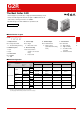
G2R PCB Power Relay
G
2
R
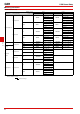
■Dimensions
** Average value
** 0.3 (-H Type)
12 3
54
3.5 3.5
(2.7)
20(2.1)
10.5**0.5
0.16
0.3
4
(0.3)
25.5 max.
(25.3)*
29 max.
(28.8)*
13 max.
(12.7)*
7.5
Five, 1.3-dia.
holes
(No coil polarity)
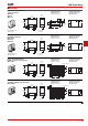
Relays with PCB Terminals
(SPDT (1c) Relays)
G2R-1(-Z)
G2R-1Z
G2R-1-H
PCB Mounting Holes
(BOTTOM VIEW)
Tolerance: ±0.1 mm
Terminal Arrangement/
Internal Connections
(BOTTOM VIEW)
This illustration is the
G2R-1 model.
** Average value
** 0.3 (-H Type)
1 3
54
3.5
(2.7)
20(2.1)
10.5**0.3
0.16
4
(0.3)
25.5 max.
(25.3)*
29 max.
(28.8)*
13 max.
(12.7)*
7.5
Four, 1.3-dia.
holes
(No coil polarity)
Relays with PCB Terminals
(SPST-NO (1a) Relays)
G2R-1A(-Z)
G2R-1AZ
G2R-1A-H
PCB Mounting Holes
(BOTTOM VIEW)
Tolerance: ±0.1 mm
Terminal Arrangement/
Internal Connections
(BOTTOM VIEW)
This illustration is the
G2R-1A model.
123
76
4
8 5
* Average value
0.3 10.5
0.16
0.3
4
(0.3)
25.5 max.
(24.9)*
29 max.
(28.6)*
13 max.
(12.6)*
2.5
2.5
(2.1)
20
(2.1)55
(2.7)
7.5
Eight, 1.3-dia. holes
(No coil polarity)
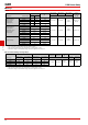
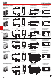
Relays with PCB Terminals
(SPDT (1c) /High-capacity Relays)
G2R-1-E(Z)
PCB Mounting Holes
(BOTTOM VIEW)
Tolerance: ±0.1 mm
Terminal Arrangement/
Internal Connections
(BOTTOM VIEW)
1 3
6
4
8 5
* Average value
0.3
0.16
0.3
4
(0.3)
25.5 max.
(24.9)*
29 max.
(28.6)*
13 max.
(12.6)*
2.5
2.5
(2.1)
20
(2.1)5
(2.7)
7.5
Six, 1.3-dia. holes
1
(No coil polarity)
Relays with PCB Terminals
(SPST-NO (1a)/High-capacity Relays)
G2R-1A-E(Z)
PCB Mounting Holes
(BOTTOM VIEW)
Tolerance: ±0.1 mm
Terminal Arrangement/
Internal Connections
(BOTTOM VIEW)
Note: Orientation marks are indicated as follows: