G2R PCB Power Relay The Best Seller G2R • 1General purpose power Relays of single-pole10 A and double-pole 5 A. • Safety-oriented design with dielectric strength of 5,000 V between coil and contacts, and surge resistance of 10,000 V. • AC and DC types are both available for operational coils. RoHS Compliant ■Model Number Legend G2R- @ - @ @ @@ -@@ — ———— —— 1 2 3 4 5 6 7 1. Relay Function None: Single-side stable K : Double-winding latching 4. Contact Type None: Single Z : Bifurcated contact 2.
G2R PCB Power Relay ■Ordering Information ● PCB Terminal Models Number of poles Classification Enclosure rating Contact form 1-pole Model Rated coil voltage 2-pole Model 12, 24, 100/(110) VAC NO G2R-1A 200/(220) VAC 5, 6, 12, 24, 48 VDC G2R-2A 100 VDC Flux protection NO/NC G2R-1 General-purpose NO G2R-1A4 Fully sealed NO/NC G2R-14 High-sensitivity Flux protection Double-winding latching 200/(220) VAC 5, 6, 12, 24, 48 VDC 100 VDC 12, 24, 100/(110) VAC 12, 24, 100/(110) VAC 200/(220)
G2R PCB Power Relay ● Quick-connect Terminal (#187) Number of poles Classification Enclosure rating Contact form 1-pole Model Rated coil voltage 12, 24, 100/(110) VAC NO General-purpose G2R-1A-T 200/(220) VAC 5, 6, 12, 24, 48 VDC 100 VDC Unsealed 12, 24, 100/(110) VAC NO/NC G2R-1-T 200/(220) VAC 5, 6, 12, 24, 48 VDC 100 VDC ● Full-wave Rectifier Number of poles Classification Enclosure rating Contact form NO 1-pole Model G2R-1A-Z Flux protection NO/NC G2R-1-Z General-purpose NO G2R-1A4
G2R PCB Power Relay ■Ratings ● Coil Item Classification • • • • Rated voltage General-purpose Quick-connect Fully sealed High-capacity Rated current (mA) 50 Hz 12 VAC 93 75 24 VAC 46.5 37.5 100/(110) VAC 11 200/(220) VAC 5 VDC • • • • • General-purpose High-capacity Bifurcated contact Quick-connect Fully sealed • High-sensitivity 5.5 Must operate voltage (V) Must release voltage (V) Max. voltage (V) Power consumption (VA, W) % of rated voltage 65 260 9/(10.6) 4,600 4.5/(5.
G2R PCB Power Relay ● Contacts Classification Number of poles Load Item General-purpose Quick-connect Terminal (1single-pole type) 1-pole High-capacity Bifurcated contact 1-pole 2-pole 2-pole High-sensitivity 1-pole 2-pole Inductive Inductive Inductive Inductive Inductive Inductive load load load load load load Resistive Resistive Resistive Resistive Resistive Resistive (cosφ = 0.4; (cosφ = 0.4; (cosφ = 0.4; (cosφ = 0.4; (cosφ = 0.4; (cosφ = 0.
G2R PCB Power Relay ■Characteristics ● Standard Relays Item Number of poles Contact resistance *1 Time *2 Set Min. set pulse width Time *2 Reset Min. reset pulse width Max. operating Mechanical frequency Electrical Insulation resistance *3 Between coil and contacts Between contacts of different polarity Dielectric Between contacts strength of the same polarity Between set and reset coils Malfunction Destruction Shock resistance 1-pole 2-pole 30 mΩ max. 50 mΩ max. 20 ms max. 30 ms 20 ms max.
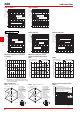
G2R PCB Power Relay G2RK-2A, G2RK-2 Switching current (A) Switching current (A) G2RK-1A, G2RK-1 50 10 AC resistive load 5 50 10 5 AC resistive load 3 AC inductive load (cosφ = 0.4) DC resistive load 1 0.5 AC inductive load (cosφ = 0.4) DC resistive load 1 0.5 DC inductive load (L/R = 7 ms) DC inductive load (L/R = 7 ms) 0.1 0.
G2R PCB Power Relay G2RK-2A, G2RK-2 Durability (x104 operations) 1,000 500 300 100 250 VAC/30 VDC resistive load 50 250 VAC inductive load (cosφ = 0.4) 30 1,000 500 300 250 VAC/30 VDC resistive load 100 30 VDC inductive load (L/R = 7ms) 50 250 VAC inductive load (cosφ = 0.4) 30 10 10 5 5 30 VDC inductive load (L/R = 7ms) 3 3 1 2 2.5 3 3.5 4 5 0 6 1 1.5 2 2.5 Switching current (A) G 2 R 1,000 500 300 250 VAC/30 VDC resistive load 250 VAC inductive load (cosφ = 0.
G2R PCB Power Relay ■Dimensions Relays with PCB Terminals (SPDT (1c) Relays) G2R-1(-Z) G2R-1Z G2R-1-H Terminal Arrangement/ Internal Connections (BOTTOM VIEW) PCB Mounting Holes (BOTTOM VIEW) Tolerance: ±0.1 mm 13 max. (12.7)* 29 max. (28.8)* 3.5 3.5 (2.7) 25.5 max. (25.3)* 1 2 3 7.5 Five, 1.3-dia. holes (0.3) (2.1) 4 0.5 0.5** 5 20 4 (No coil polarity) 1 0.3 This illustration is the G2R-1 model. 0.
G2R PCB Power Relay Relays with PCB Terminals (SPDT (1c) Relays) G2R-14(-Z)(-U) G2R-1Z4 13.5 max. (12.9)* 29 max. (28.6)* Terminal Arrangement/ Internal Connections (BOTTOM VIEW) PCB Mounting Holes (BOTTOM VIEW) Tolerance: ±0.1 mm 3.5 3.5 25.5 max. (24.8)* (2.7) 1 2 3 7.5 Five, 1.3-dia. holes 4 0.5 0.5 1 (2.1) 5 20 (No coil polarity) 0.3 0.
G2R PCB Power Relay Relays with PCB Terminals (DPDT (2c) Relays) G2R-2(-Z) G2R-2-H 13 max. (12.7)* 29 max. (28.8)* Terminal Arrangement/ Internal Connections (BOTTOM VIEW) PCB Mounting Holes (BOTTOM VIEW) Tolerance: ±0.1 mm Eight, 1.3-dia. holes 2.5 2.5 (2.7) 25.5 max. (25.2)* 1 2 3 4 8 7 6 5 7.5 (0.3) (No coil polarity) 4 0.5 0.5 1 0.3 (2.1) 0.15 Relays with PCB Terminals (DPST-NO (2a) Relays) G2R-2A G2R-2A-H G2R-2A-Z 5 * Average value (2.
G2R PCB Power Relay Relays with Quick-connect Terminals (SPDT (1c) Relays) 7.5 G2R-1-T 30.5 max. (29.7)* 5.2 Terminal Arrangement/ Internal Connections (BOTTOM VIEW) Mounting Holes (BOTTOM VIEW) Tolerance: ±0.1 mm 5.2 17.5 * Average value Five, 1.3-dia. holes 4.75 0.5 38 Two M3 or two 3.5 dia. 1 8.5 2 4 3 5 29.5 max. (No coil polarity) Note: Model number of quick-connect terminal is 187. 2.5 Relays with Quick-connect Terminals (SPST-NO (1a) Relays) 7.5 G2R-1A-T 45 max. (43.9)* 14 max.
G2R PCB Power Relay ■Approved Standards • The approval rating values for overseas standards are different from the performance values determined individually. Confirm the values before use. File No. E41643 CSA Certified: File No.
G2R PCB Power Relay ■Precautions ● Please refer to “PCB Relays Common Precautions” for correct use. Correct Use ● Mounting • When mounting a number of relays on a PCB, be sure to provide a minimum mounting space of 5 mm between the two juxtaposed relays as shown below. 5 mm min. Type #187 (Width 4.75) 5 mm min. G 2 R Refer to the following table for examples of positive-lock connectors made by AMP. Contact the manufacturer directly for details on connectors including availability.