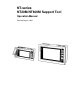
NT-series NT20M/NT600M Support Tool Operation Manual Revised August 1993
Notice: OMRON products are manufactured for use according to proper procedures by a qualified operator and only for the purposes described in this manual. The following conventions are used to indicate and classify precautions in this manual. Always heed the information provided with them. Failure to head precautions can result in injury to people or damage to the product. DANGER! Indicates information that, if not heeded, is likely to result in loss of life or serious injury.
TABLE OF CONTENTS SECTION 1 Introduction . . . . . . . . . . . . . . . . . . . . . . . . . . . . . . . . . . . . . 1-1 1-2 1-3 1-4 1-5 1-6 1-7 1-8 1-9 1-10 1-11 1-12 1-13 1-14 1-15 Terminology and NT-series Manuals . . . . . . . . . . . . . . . . . . . . . . . . . . . . . . . . . . . . . . . . . . Using Older Models . . . . . . . . . . . . . . . . . . . . . . . . . . . . . . . . . . . . . . . . . . . . . . . . . . . . . . . System Configuration . . . . . . . . . . . . . . . . . . . . . . . . . . . . . . .
SECTION 5 Printing . . . . . . . . . . . . . . . . . . . . . . . . . . . . . . . . . . . . . . . . . 5-1 5-2 5-3 Printing Features . . . . . . . . . . . . . . . . . . . . . . . . . . . . . . . . . . . . . . . . . . . . . . . . . . . . . . . . . Printing from the File Selection Display . . . . . . . . . . . . . . . . . . . . . . . . . . . . . . . . . . . . . . . Printing from the Screen Selection Display . . . . . . . . . . . . . . . . . . . . . . . . . . . . . . . . . . . . . SECTION 6 Transmitting Data .
About this Manual: This manual describes the installation and operation of the Support Tool and includes the sections described below. The Support Tool is a software package for creating and managing displays for the NT20M and NT600M Programmable Terminals (PTs). Please read this manual completely and be sure you understand the information provided before attempting to install and operation the Support Tool. Section 1 provides an overview of Support Tool operation and its operating environment.
SECTION 1 Introduction This section outlines the operations of the Support Tool. It includes general operating procedures and installation procedures, as well as miscellaneous information, such as the functional limitations when creating screens for older PT models. Refer to the other sections in this manual for details on specific operations. Reference pages are given in this section for many operations.
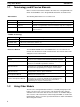
Section 1-2 Using Older Models 1-1 Terminology and NT-series Manuals Names of items in this manual related to the NT Series of Programmable Terminals and SYSMAC C-series Programmable Controllers are defined next. Abbreviations The following abbreviations are used in the text. Abbreviation Term Meaning PT Programmable Terminal Refers to an OMRON NT-series Programmable Terminal.
Section 1-3 System Configuration Host Interface Unit and/or System ROM Host Interface Units NT20M-LK201-EV1 NT20M-LK202-EV1 NT20M-LK203-EV1 NT20M-RT121-EV1 System ROM NT600M-SMR01-E Unsupported features Lamps and touch switches Lamp flashing for bit input designations Round lamp displays 3D frame displays for touch switch Reverse video display for touch switch inputs Mark input for labels Bar graphs Vertical displays Enlarged display widths (2 to 255 dots) +/– displays Enlarged percentage displays Num
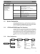
Section 1-4 Creating a Work Disk 1-3-3 Support Tool System Model NT20M-ZA5AT-EV4 System disk 3.5-inch (2DD) and 5-inch (2HD) disks Applicable computers IBM PC/AT or IBM PC/AT compatible (note 1) Floppy disk drives necessary One min. (note 2) Graphic monitor VGA Printer Epson dot matrix or HP laser printer PROM writer Commercially available PROM writer (note 3) Mouse Serial mouse (note 4) MS-DOS Version 3.3 or later Note 1. The computer must have 640 KB of memory. 2.
Section 1-6 Main Menu 5. Input NTMreturn to start and use the Support Tool. C > NTM This completes the backup. When starting up the next time, change directories to the NT directory and then input “NTM” to start the Support Tool. C >CD \NT C > NTM 1-5 Starting and Exiting Startup Procedure If working from a floppy, insert the start-up disk into disk drive A and a data disk into disk drive B, then turn on the power.
Section 1-7 File Selection 1-7 File Selection When you select Edit Screen from the Main Menu, the File Selection Display is displayed. Move the bar cursor to the desired file name and press the Enter Key, or click the desired file name once to move the bar cursor and then again to open the file. Each file contains screen data, memory table data (for numeral and character string tables), and mark data for a maximum of 250 screens for the NT20M or 1,000 screens for the NT600M.
Section 1-8 Screen Selection File Operations Function key You can perform file operations by using the function keys while the File Selection Display is being displayed. Name Function Page F1 Copy Copies the contents of one file to another file. 96 F2 Delete Completely deletes the contents of a file. 97 F3 Print Prints screen images or data, and cross references of character string and numeral table usage.
Section 1-8 Screen Selection Screen Selection Display Screen Status Symbols displayed in the status column (A to E, !) express screen attribute settings for the each screen. Symbols displayed in the status column are explained in more detail in the Screen Status box, which is in the lower right-hand corner of the screen. Symbol Meaning (Blank) No data Indicates a screen for which no data has been created. ! Data exists Indicates a screen for which data has been created.
Section 1-8 Screen Selection You can perform screen operations by using the function keys while the File Selection Display is displayed. Screen Selection Operations Function key Name Function Page F1 Copy Copies previously created screen data to another screen number. 90 F2 Delete Deletes designated screen data. Can also be used to delete multiple screens, or to delete screens from the Programmable Terminal one screen at a time. 91, 114 F3 Print Prints designated screen data.
Inputting Screen Comments, File Names, and Titles 1-9 Section 1-9 Inputting Screen Comments, File Names, and Titles Screen comments, file names, and file titles can be input whenever new screens are created or when existing screens are modified. The methods for inputting these are described in this section. 1-9-1 Screen Comments Screen comments can be input or changed when shifting from the Edit Display to the Screen Selection Display. Use the following procedure. 1, 2, 3... 1.
Section 1-10 Editing Screens 1-10 Editing Screens If you select a screen number from the Screen Selection Display, the Initial Edit Display will be displayed. If the NT20M has been selected with Tool Settings, then the NT20M screen image display area will be shown in the rectangular box at the top of the display. If the NT600M has been selected, then the entire display becomes a display area and this box will not appear.
Section 1-11 Inputting Character Strings and Numbers Item Function Page Extended Functions (EXTEND) Enables usage of stand-alone operation. In stand-alone operation, screens can be changed from PT touch switches/function keys or from Expansion I/O Units. 85 Sets data area allocations, comments, and other information for use with direct connection operation. This function key appears only if direct connection has been turned ON in the Tool Settings.
Section 1-12 Basic Operation In overwrite mode, the cursor becomes a reversed rectangle and character strings delete previously input characters at the cursor position. Inputting Numbers Inputting numbers is basically the same as inputting character strings, except that you cannot change between insert mode and overwrite mode with the Insert Key. The overwrite mode is always used.
Section 1-12 Basic Operation 1-12-2 Screen Buttons There are many buttons in the shape of keys that can appear during Support Tool operation. These buttons can be clicked with the mouse to achieve the same operation as the equivalent keyboard keys. Included are the Enter Key (carriage return arrow), Escape Key, cursor keys, PgUp Key, PgDn Key, Space Bar, Shift+Home (clear) Key (one button combining two keys), the Home (clear) Key, and function keys.
Section 1-13 Tool Settings 1-13 Tool Settings If you start up the Support Tool and select Tool Settings from the Main Menu, the Tool Settings Display will appear. Contents of Tool Settings Name Content NT Model Sets the model of Programmable Terminal being used. Memory Size Sets the memory capacity of the Programmable Terminal. Direct Setting Turns ON and OFF the direct connection operation. Refer to page 17 for details. Printer Sets the printer model to be used.
Section 1-14 Environment Settings “No” to save time. You can manually rewrite the screen by pressing the Tab Key during operation. Temporary Directory The Support Tool will create a temporary work file when creating screens or transferring data to or from ROM. Most write operations are performed on this temporary file. To increase overall operating speed, this file should be created on your hard disk or in RAM. Tool Settings File File settings are saved in the root directory for the Support Tool, i.e.
Section 1-15 Direct Connection Item Display y grid g Snap ON function Lamp/touch switch number di l display Settings Setting No Display grid is not displayed. 8-dot 16-dot 32-dot Display grid is displayed at the specified width. Screen objects can be snapped to the grid if one of these settings is made and the snap ON function is turned ON (see below). Touch switch Display grid is displayed at the minimum width for touch switches.
Section 1-15 Direct Connection 4. 5. 6. Create the required screens, making all settings required for direct connection. Save the screens. Transfer the screens to the PT or write them to ROM. Conversion Screen files that were created with direct connection turned OFF can be loaded with direct connection turned ON to convert the screens for use with direct connection.
Section 1-15 Direct Connection 1-15-2 Direct Connection Information Settings for the direct connection information are made from the extended functions display. Direct connection information settings will not appear on the extended function display unless direct connection is turned ON in the Tool Settings. Use the following procedure to set the direct connection information settings. 1, 2, 3... 1. Specify EXTEND from the Initial Edit Display.
SECTION 2 Creating Screens This section describes the procedures used to create and check screens and to input screen attributes. The procedures for creating special display characters, called marks, and for controlling screens during stand-alone operation are also provided here. 2-1 2-2 2-3 2-4 2-5 2-6 2-7 2-8 2-9 2-10 2-11 2-12 2-13 2-14 2-15 2-16 Inputting Character Strings . . . . . . . . . . . . . . . . . . . . . . . . . . . . . . . . . . . . . . . . . . . . . . . . .
Section 2-1 Inputting Character Strings 2-1 Inputting Character Strings With the Character Input Display, you set characters to be displayed on the PT. You set character sizes, character scaling factors, manner of display, and display positions. If you select STR IN from the Initial Edit Display, the Initial Character Input Display will appear. Initial Character Input Display The following pages explain how to use this display, taking the creation of NT20M screen data as an example.
Section 2-1 Inputting Character Strings 3. If the input is correct, press the Enter Key to enter the characters and go to the String Attributes section on page 24. Special characters or Marks can also be input as display characters as described below. Special Characters Characters not on the keyboard can be input via character codes. A list of character codes is provided at the end of the manual. To input a character code, press the ALT Key followed by the decimal code.
Section 2-1 Inputting Character Strings String Attributes Here you set the size, scale, and attributes for character strings that have been input. 1, 2, 3... 1. 2. 3. Set the size to be used for each 1-byte character. Set the scale factor for the characters. NT600M strings can be set to 64X in addition to the ones shown in the above display. Set display attributes. “Spot” is for flashing characters in reverse video. Display attributes will be displayed on the computer screen as shown below.
Section 2-1 Inputting Character Strings displayed. You cannot set a display position that allows the guide box to extend off the screen. Guide box Cross-shaped cursor 2-1-2 2. When you have set the display position, press the Enter Key. 3. You will be returned to the Initial Text Input Display, and the contents set up to this point are displayed. At this time, a message again appears in the command box instructing you to enter text.
Section 2-1 Inputting Character Strings 1, 2, 3... 1. Specify DELETE. The cross-shaped cursor will be displayed. 2. Line up the center of the cross-shaped cursor with the string you want to delete, and press the Enter Key. The string which you have selected will be outlined by a guide box. A message will appear in a comment box to verify whether you actually want to delete that string.
Section 2-1 Inputting Character Strings 1, 2, 3... 1. Press MODIFY. The cross-shaped cursor will be displayed. 2. Line up the center of the cross-shaped cursor with the string you want to change, and press the Enter Key. The character which you have selected will be outlined by a guide box, and at the right of the screen a box will be displayed for you to select the items to be modified. 3. Use the Up and Down Keys to select the item to modified, and then press the Enter Key.
Section 2-2 Numeral Displays 2-2 Numeral Displays Values from numeral tables can be displayed on a screen. The numeral table entry to be referenced, the display position, and the manner of display are set. You can set a maximum of 50 numeral displays per screen. For the NT20M, numeral table entries are numbered from 0 to 127, for a total of 128. For the NT600M, numeral table entries are numbered from 0 to 255, for a total of 256.
Section 2-2 Numeral Displays input –123.456, then just input –123456. The distinction between the integer portion and the decimal portion is specified in the next step. Input the number, and then press the Enter Key. Numeral Display Settings Set the way in which the display will appear on the screen. Refer to the examples on page 30.
Section 2-2 Numeral Displays Reference table entry (Reference Table) Set the number of the item to be referenced in the numeral table. Number of integer digits (Integer) Set the number of digits for the integer portion of the number. Number of decimal digits (Decimal) Set the number of digits for the decimal portion of the number. Zero suppress (Zero Sup) Set whether or not leading zeros are to be displayed on the screen.
Section 2-2 Numeral Displays Designating Display Positions A guide box corresponding to the size of the numeral display will appear. Designate the display position on the screen with the cross-shaped cursor and press the Enter Key. You cannot make a setting that will cause the guide box to extend from the screen. Deleting and Modifying You can delete or modify previously input numeral displays. The procedures for these operations are the same as those for deleting and modifying character strings.
Section 2-2 Numeral Displays 3. Specify “Direct.” Indirect referencing is not currently supported. The numeral table will be displayed. 4. Specify the desired table entry number. The initial value input field (contents) will be entered. The headings in the table are described in the following table. Heading 5. 32 Meaning No. Numeral table entry number Contents Initial value IN initialize at startup) Indicates whether or not the table value is to be initialized when the PT is turned ON.
Section 2-2 Numeral Displays Note Negative values and initial values are set differently for direct connection. Refer to page 61 for details. 6. Make the four settings as described in the following table. The comment is optional and all four settings can be omitted here if desired and input later using the table edit operation. Heading Meaning Initialize (Init) Set YES to initialize the contents in the numeral table when PT power is turned ON.
Section 2-3 Character String Displays Number of integer digits (Integer) Set the number of digits for the integer portion of the number. Number of decimal digits (Decimal) Set the number of digits for the decimal portion of the number. Zero suppress (Zero Sup) Set whether or not leading zeros are to be displayed on the screen. Display sign (Disp Sign) Set whether or not negative signs are to be displayed on the screen. The positive sign is not displayed.
Section 2-3 Character String Displays 2-3-1 Normal Character String Displays If you select STR DISP from the Initial Edit Display, the Initial Screen for Character String Display will appear. Initial Display for Character String Display Designating String Tables to be Referenced Table entires 0 to 13 are displayed first on the screen. To display the next entires, press the Pg Dn Key; to return to previously entries, press the Pg Up Key.
Section 2-3 Character String Displays Setting Display Attributes Set the way in which the display will appear on the screen. Number of character digits (Char; See Note) Set the number of character digits to be displayed on the screen. Character size (Size) Set the character size to be used for each 1-byte characters. Scale Set the scale for characters to be displayed on the screen. The NT600M can be set to 64X in addition to those shown above. Display attributes (Attr.
Section 2-3 Character String Displays and press the Enter Key. You cannot make a setting that will cause the guide box to extend from the screen. Deleting and Modifying 2-3-2 Creating You can delete or modify previously input character string displays. The procedures for these operations are the same as those for deleting and modifying character strings. Refer to appropriate subsections of 2-1 Inputting Character Strings for details.
Section 2-3 Character String Displays 3. Specify “Direct.” Indirect referencing is not currently supported. The character string table will be displayed. 4. Specify the desired table entry number. The initial value input field (contents) will be entered. The headings in the table are described in the following table. Heading 5. 38 Meaning No.
Section 2-3 Character String Displays value field is left, the following display will appear to input the remaining settings. 6. Make the four settings as described in the following table. The comment is optional and all four settings can be omitted here if desired and input later using the table edit operation. Heading Meaning Initialize (Init) Set YES to initialize the contents in the character string table when PT power is turned ON.
Section 2-4 Lamps Number of character digits (Char; See Note) Set the number of character digits to be displayed on the screen. Character size (Size) Set the character size to be used for each 1-byte characters. Scale Set the scale for characters to be displayed on the screen. Display attributes (Attr.) Set display attributes for the screen. Refer to page 24 for examples of how attributes are displayed on screen.
Section 2-4 Lamps Designating Area The size and display position of the lamp must be specified. The lamp area is set by designating diagonal corners (the starting and ending points) of a rectangle for square lamps and the center and radius of circular lamps. Starting point Radius Center Ending point 1, 2, 3... 1. 2. Designate the starting point or center. Designate the ending point or radius The lamp settings are input after the lamp area has been designated.
Section 2-4 Lamps Inputting the Label If you set label to “Yes,” the following screen will be displayed. If you set label to “No,” you will be returned to the Initial Lamp Display. Input the label and press the Enter Key. You can also press the F3 Function Key to input from a list of marks that have been created. Refer to page 22 for details on the mark input procedure. Note 1. Labels can be only one line long. Input character strings if longer labels are required. 2.
Section 2-4 Lamps 2-4-2 Creating Direct Connection Lamps Use the following procedure to create a direct connection lamp. 1, 2, 3... 1. Select LAMP from the Initial Edit Display, a list of the lamps already existing in the current screen will be displayed. 2. Specify the number to be used in the table. The numbers in this table are not the lamp numbers. When a number is specified, a display to specify either a rectangular or round lamp will appear. 3. 4. Specify the lamp shape.
Section 2-4 Lamps nate the center and one point on the circumference of the circle. A display will appear to specify the bit that is to control the lamp. 5. 6. 7. Input the address of the PC bit that is to control the lamp. Timer/counter numbers cannot be specified. DM word address can also be specified, followed by the bit number within the word. Input a comment if desired. The comment is for user use only. The lamp settings will appear when the above display is left.
Section 2-4 Lamps 8. Press the Enter Key after completing all of these settings. If you set label to “Yes,” the following screen will be displayed. If you set label to “No,” you will be returned to the Initial Lamp Display. Input the label and press the Enter Key. You can also press the F3 Function Key to input from a list of marks that have been created. Refer to page 22 for details on the mark input procedure. Note 1. Labels can be only one line long.
Section 2-5 Touch Switches LETE or MODIFY. The modification procedure is basically the same as the creation procedure given above. 2-5 Touch Switches A touch switch can be set by designating the size, display position, and a label. You can set a maximum of 64 touch switches per screen for the NT20M and 128 for the NT600M. The procedure for creating touch switches depends on whether or not direct connection is ON or OFF in the Tool Settings. Both procedures are given below.
Section 2-5 Touch Switches Touch Switch Settings Switch number The number of the switch being set. (The numbers, 0 to 255, are used in common with lamps. The same number cannot be used more than once.) Frame Whether or not switch frames are to be displayed when switch are displayed. If “No” is designated, the switches will be indicated by dotted lines on the Support Tool display. Either or normal or solid frame can also be designated.
Section 2-5 Touch Switches Note 1. Labels can be only one line long. Input character strings if longer labels are required. 2. “@” will be input as the default label if the label setting is changed from NO to YES. Set the size and scale of the label display. Position the label on the screen. Deleting and Modifying You can delete or modify previously input touch switch data on the screen. The procedures for these operations are the same as those for deleting and modifying character strings.
Section 2-5 Touch Switches 2. 3. 4. 5. 6. 7. Specify the number to be used in the table. The numbers in this table are not the touch switch numbers. A display will appear to draw the touch switch. Specify the starting and ending points (diagonally opposed corners) of the rectangle. A display will appear to specify the bit that is to control the touch switch. Input the address of the PC bit that is to control the touch switch. Timer/ counter numbers cannot be specified.
Section 2-5 Touch Switches The touch switch settings will appear when the above setting has been made. 8. Set the way in which the display will appear on the screen. Frame Whether or not a switch frame is to be displayed when the switch is displayed. If “No” is designated, the switch will be indicated by dotted lines on the Support Tool display. Either or normal or solid frame can also be designated. Inverse Whether an inverse display will appear when the touch switch is input.
Section 2-6 Bar Graphs Note 1. Labels can be only one line long. Input character strings if longer labels are required. 2. “@” will be input as the default label if the label setting is changed from NO to YES. Set the size and scale of the label display. Position the label on the screen. When touch switch settings have been completed, you can return to set another touch switch or you can continue pressing the Escape Key to return to the Initial Edit Display.
Section 2-6 Bar Graphs 2-6-1 Creating Normal Bar Graphs If you select BAR GRPH from the Initial Edit Display, the Initial Bar Graph Display will appear. Initial Bar Graph Display Designating Display Position A bar graph is set by designating both ends (the starting and ending points) of a diagonal line across the bar graph. It makes no difference whether the display position of a bar graph is designated from the right or left, or from the top or bottom.
Section 2-6 Bar Graphs Setting the Numeral Table Reference Specify the entry number of the numeral table to be referenced for the bar graph. Inputting Initial Value Set the initial value and then press the Enter Key.
Section 2-6 Bar Graphs Display Settings Set all the bar graph display attributes and press the Enter Key. Direction Whether the bar is to be displayed in the normal direction or the reverse direction. (See note 1.) Width The width of the bar graph. The width must be 3 dots or greater to set a frame. The width must be 8 dots or greater when displaying horizontal bars from the top of the screen or when displaying vertical bars from the right of the screen.
Section 2-6 Bar Graphs Displaying –60% Without sign 0% With sign –60% 3. The following relationship exists between the number of display dots on the screen, the content of the numeral table reference, and the 100% value.
Section 2-6 Bar Graphs 2. 3. 4. 5. This is not the numeral table entry number. M Tbl: The numeral table entry number being used. Rf: The access method for the numeral table (direct or indirect) Dr: The direction of the bar. %: Whether or not the percentage display is being used. Specify the number to be used in the table. This is not the numeral table and the numbers do not correspond to item numbers in the numeral table.
Section 2-6 Bar Graphs Note Negative values and initial values are set differently for direct connection. Refer to page 61 for details. 7. Make the four settings as described in the following table. The comment is optional and all four settings can be omitted here if desired and input later using the table edit operation. Heading Meaning Initialize (Init) Set YES to initialize the contents in the numeral table when PT power is turned ON.
Section 2-6 Bar Graphs Direction Whether the bar is to be displayed in the normal direction or the reverse direction. (See note 1.) Width The width of the bar graph. The width must be 3 dots or greater to set a frame. The width must be 8 dots or greater when displaying horizontal bars from the top of the screen or when displaying vertical bars from the right of the screen. Graph Frame Whether or not a graph frame showing 100% is to be displayed.
Section 2-7 Editing Memory Tables Deleting and Modifying 2-7 Direct connection bar graphs are deleted or modified from the display shown in step 1. above. Select the number of the numeral table and then specify DELETE or MODIFY. The modification procedure is basically the same as the creation procedure given above. Editing Memory Tables Memory tables can be displayed for editing or to create lists of screen numbers referencing a specified table entry.
Editing Memory Tables Section 2-7 on the screen. To display entries 64 and up, press the Pg Dn Key; and to return to previously displayed entries, press the Pg Up Key. Note If you press F1 (Reference) at this time, a list of the screens referencing the table entry indicated by the cursor will appear. 1, 2, 3... 1. With the cursor, select the numeral table entry that you want to edit, and press the Enter Key. 2. Input the new value and press the Enter Key. 3.
Section 2-7 Editing Memory Tables 1, 2, 3... 1. 2. 3. With the cursor, select the string table entry that you want to edit, and press the Enter Key. Input the character string and press the Enter Key. When you are finished editing, press the Escape Key. List of Referencing Screens You can display a list of screens referencing designated number or string table entries by pressing F1 when the numeral or string table is displayed.
Section 2-8 Numeral Editing 3. You can continue inputting or changing setting for other string table entires when finished with the first one. When you are finished editing, press the Escape Key. 4. Words and Numeric Data When setting word addresses for numeral or string tables, the number of PC words to be used and the address of the first word are input.
Section 2-8 Numeral Editing 3. The Numeral Editing function uses the lower portion of the display. When numeral editing is set on a screen where characters and numerals are displayed, the characters and/or numerals may be hidden. 2-8-1 Normal Numeral Editing If you select NUM EDIT from the Initial Edit Display, the following display will appear. Initial Numeral Editing Display The headings have the following meanings: No.: M Tbl: Snd: Inp: Dsp: The order that has been set for numeral editing.
Section 2-8 Numeral Editing When the initial value is designated, the number of digits input and the number of digits transmitted to the host are set. Input and Transmission Digits Input digits (Input Col) Set the number of digits that can be input via touch switches or function keys. You can set from 1 to 8 digits. Transmission Digits (Sending) Set the number of digits that are transmitted to the host. You can select either 4 or 8 digits.
Section 2-8 Numeral Editing Deleting Numeral Editing You can delete numeral edit settings that have already been made. 1, 2, 3... 1. To delete a numeral editing setting, move the bar cursor to the setting you want to delete on the Initial Display for Numeral Editing and then press the Enter Key. 2. Press F1 (Delete). A confirmation prompt will be displayed on the screen. Note 1. If a numeral display is set for the selected numeral edit settings, then those settings will be shown in a guide box. 2.
Section 2-8 Numeral Editing Changing the Order of Numeral Editing You can change the order of numeral edit settings that have already been made. 1, 2, 3... 1. 2. 3. Press F2 (Change Order). A list of numeral edit settings will be displayed on the screen. Move the bar cursor to the numeral edit setting for which you want to change the order, and press the Space Key. The new order will be displayed in the order column.
Section 2-8 Numeral Editing Touch Panel PTs (DT___) Key Touch switch Key Touch switch Key Touch switch 0 231 9 240 . 249 1 232 A 241 HOME 250 2 233 B 242 251 3 234 C 243 252 4 235 D 244 253 5 236 E 245 254 6 237 F 246 ENTER 255 7 238 CLR 247 --- --- 8 238 +/– 248 -–– --- Note Touch switches 0 through 230 are used for numeral editing screens. Keys A through F cannot be used for the keypad even if they are set.
Section 2-8 Numeral Editing Numeral editing is not possible for PTs without Touch Panels is Expansion I/O Units with 10/02 Terminals are used. 2-8-2 Creating Direct Connection Numeral Editing Use the following procedure to create a direct connection numeral editing area. 1, 2, 3... 1. 68 Select NUM EDIT from the Initial Edit Display, a list of the numeral editing already existing in the current screen will be displayed. 2. Specify the number to be used in the table.
Section 2-8 Numeral Editing Heading 4. Meaning No. Numeral table entry number Contents Initial value IN (initialize at startup) Indicates whether or not the table value is to be initialized when the PT is turned ON. # (quantity) Number of PC words used Word Address of the first PC word Comment User comment area Input the desired initial value. This value can be omitted here if desired and input later using the table edit operation. The initial value can be up to 8 digits long.
Section 2-8 Numeral Editing The numeral editing settings will appear when the above display is left. 6. Set the way in which the display will appear on the screen. Refer to the examples on page 30. Number of integer digits (Integer) Set the number of digits for the integer portion of the number. Number of decimal digits (Decimal) Set the number of digits for the decimal portion of the number. Zero suppress (Zero Sup) Set whether or not leading zeros are to be displayed on the screen.
Section 2-9 Polylines PT Bit input disabled Bit input enabled DF___ or DN___ with 12-key Function Key Unit F1 through F12 can be used. Numeral editing is not possible. DN___ with 32/16 Terminal F1 through F12 and F17 through F29 can be used. F13 through F16 are used as system keys. Numeral editing is not possible. F13 through F16 are used as system keys. DT___ Touch switches 231 through 255 can Touch switches 231 through 255 can be used for numeral editing input keys.
Section 2-9 Polylines 4. 5. 2-9-2 Designate the ending point for the polyline. Press the Shift and Enter Keys or double-click the left mouse button to indicate that the ending point has been entered. Deleting Polylines You can delete polylines set on the screen. 1, 2, 3... 1. 2-9-3 Specify DELETE. The starting points for all of the polylines on the screen will be indicated by small squares. 2. To delete a polyline, specify the starting point for that line.
Section 2-10 Circles 3. 2-10 You can move the cross-shaped cursor to the starting point of the designated polyline and then make additions or modifications in the same way as when creating new polylines. Circles Circles can be created on the screen. The amount of circle data for a screen depends only on the amount of memory remaining. Select GRAPHIC from the Initial Edit Display to access the Graphic Input Display and then select CIRCLE. The Initial Circle Display will appear.
Section 2-10 Circles 2-10-2 Deleting Circles You can delete circles set on the screen. 2-10-3 1, 2, 3... 1. Specify DELETE. The center points for all of the circles on the screen will be indicated by small squares. 2. Specify the circle you want to delete. The designated circle will be enclosed by a square frame and a message will be displayed asking whether you actually want to delete the circle. 3.
Continuous and Overlapping Screens 3. 2-11 Section 2-11 You can move the cross-shaped cursor to the perimeter of the designated circle and then modify the radius and center point in the same way as when creating new circles. Continuous and Overlapping Screens You can combine previously created multiple screens into a continuous screens by linking them or into one screen by stacking them into overlapping screens.
Continuous and Overlapping Screens Section 2-11 • The child screen has been designated for another parent screen. • No more than one child screen has been designated. Continuous Screens The screen numbers of the child screens you want to display continuously are registered next. Register the child screen numbers in the order that you want them displayed. You can register a maximum of 8 child screens. 1, 2, 3... 1. 2. 3.
Continuous and Overlapping Screens 4. Section 2-11 Set whether or not you want page numbers displayed at the host and then press the Enter Key. 5. Input the screen comment and press the Enter Key or press the Escape Key to return to step 4. Comments can be up to 24 characters. Note 1. A screen with a numeral edit settings cannot be set as a child screen. 2.
Section 2-12 Screen Attributes Note 1. When overlapping child screens with numeral displays, character string displays, lamps, touch switches, or bar graphs, be sure that these various display elements do not overlap. 2. Only screen attributes set for the parent screen will be used. Parent screen attributes will not change unless they are changed directly (i.e., changing child screen attributes will not affect parent screen attributes).
Section 2-12 Screen Attributes Attributes Function Buzzer Whether or not the buzzer is to sound when the screen is displayed. If the buzzer is set to sound, you can select either continuous or intermittent operation. History Whether or not the history of the screen is to be recorded. If you set “Yes,” then, when the Programmable Terminal (PT) is operating, all screens have been displayed will be recorded in the PT.
Section 2-13 Screen Check Screen Attribute Displays 2-13 After the settings have been made, their contents will be displayed in the status column on the screen listing as letters of the alphabet.
Section 2-13 Screen Check another continuous or overlapping screen, it results in a screen error. A check can be performed as shown below from the Screen Selection Display 1, 2, 3... 1. 2. Press NEXT, F3 (Check). A message will appear asking whether or not you want the results of the screen check to be printed out. Select “Yes” or “No” and then press the Enter Key. Regardless of whether you select Yes or No, the results will be displayed on the screen. The contents will be displayed as shown below.
Section 2-14 Marks Note 1. If there are no continuous or overlapping screens, nothing will be displayed. 2. The paper size for printing is A4 (portrait). Other settings can result in printing errors. 2-14 Marks Marks can be created for display on the PT. If you press F9 on the Screen Selection Display or specify MARK from the Initial Edit Display, the Mark Creation Display will appear. This display is split in half, with a creation display on the right and a reference display on the left.
Section 2-14 Marks The function keys are used as described in the following table. Function Keys Key Setting and Clearing Dots Key Function F1 Mark Reference (Mk Ref) Displays designated marks on the reference display. F2 Copy (Copy) Copies a designated rectangular area on the creation display to another position. F3 Reference Copy (RCopy) Copies a designated rectangular area on the reference display to a designated position on the creation display.
Section 2-14 Marks 3. Copy Press the Escape Key to return to the Creation Display. F2 is used to copy a designated rectangular area on the creation display to another position. This operation can be canceled at any point by pressing the Escape Key. Note The cursor may not be displayed on the screen when it overlaps with the starting point, ending point, etc. If you are not sure of the position of the cursor, move it with direction keys. 1, 2, 3... 1.
Section 2-15 Stand-alone Operation Operation is basically the same as for copying with F1 except that the copy is designated on the reference display and created on the creation display. Area Set F4 is used to fill in a designated area on the creation display. Area designation is basically the same as for copying with F1. Area Clear F5 is used to clear all of the dots for a designated rectangular area on the creation display. After being cleared, they are represented by small dots.
Section 2-15 Stand-alone Operation PT Limitations PT with Touch Panels (DT___) Touch switches 231 to 255 cannot be used. PT with Function Keys (DF___) Stand-alone operation is not supported. PT without Function Keys (DN___) 12-key Function Key Units Stand-alone operation is not supported. 32/16 Terminals F1 to F12 and F17 to F29 10/02 Terminals Numeral editing not supported. F1 to F10 can be used for stand-alone operation.
Section 2-16 Edit 2. 3. 4. 5. Restrictions Move the cursor to the touch switch/function key to which a screen is to be allocated. F1 will correspond to 000; F2, to 001; etc. Input the screen number to be allocated to the touch switch/function key and press the Enter Key. Repeat steps 2. and 3. until all desired screen have been set. Press the Escape Key to return to the Extended Features Display. The following touch switches/function keys can be used depending on the model of the PT.
Section 2-16 Edit 4. 5. 6. Move Use the following procedure to move existing elements on the screen. 1, 2, 3... 1. 2. 3. 4. 5. 6. Delete Specify MOVE from the Cut and Paste Display Move the cursor to designate the starting point of the move area and press the Enter Key. Move the cursor to designate the end point of the move area and press the Enter Key. The specified move area will be indicated by a dotted box. Move the cursor to designate the area to move to and press the Enter Key.
SECTION 3 Managing Screen Data This section describes how to copy and delete previously created screens, to change screen comments, and to read screen in from other files. 3-1 3-2 3-3 3-4 Copying Screens . . . . . . . . . . . . . . . . . . . . . . . . . . . . . . . . . . . . . . . . . . . . . . . . . . . . . . . . . . Deleting Screens . . . . . . . . . . . . . . . . . . . . . . . . . . . . . . . . . . . . . . . . . . . . . . . . . . . . . . . . . . Changing Screen Comments . . . . . . . . . . . . . . . .
Section 3-1 Copying Screens 3-1 Copying Screens You can copy designated screens to different screens. To copy a screen, first designate the source screen number and then designate the target screen number as described below. 1, 2, 3... 1. Go to the Screen Selection Display. 2. Move the bar cursor to the number of the screen from which data is to be copied, and then press F1 (Copy). 3. Input the number of the screen to which the data is to be copied, and then press the Enter Key.
Section 3-2 Deleting Screens you wish to cancel, return to the Screen Selection Display by pressing a key other than the Enter Key. 3-2 Deleting Screens You can delete one or more screens that has previously been set. Screen data can also be deleted from the PT. 1, 2, 3... 1. 2. 3. 4. Go to the Screen Selection Display. If you are only deleting one screen move the bar cursor to the number of the screen you want to delete, and then press F2 (Delete).
Section 3-3 Changing Screen Comments 5. 6. 3-3 To confirm deletion, press the Enter Key, or to return to step 1, press any key other than the Enter Key. When the deletion is complete, a message will be displayed. Press any key to return to the Screen Selection Display. Changing Screen Comments You can change designated screen comments. 1, 2, 3... 1. 2. 3. 92 Go to the Screen Selection Display.
Section 3-4 Reading Data from Other Files 4. 3-4 Input the new comment, and then press the Enter Key. Reading Data from Other Files Screens contained in other files can be read into the current file from the Screen Selection Display. Although entire files can be copied from the File Selection Display, copying from the Screen Selection display enables copying one screen at a time into the current file.
Section 3-4 Reading Data from Other Files 4. Specify insertion or overwriting and press the Enter Key. Note All previous data in the selected screen will be lost if overwriting is specified. 5. 6. Specify the data to be copied. You can select from screen data, mark data, number table data, character table data, direct connection information, and I/O comments. A list of the files in the data directory specified in the Tool Settings will be displayed when these settings are confirmed.
SECTION 4 Managing File Data This section describes how to manage file data, including copying and deleting files, as well as settings such as PT histories and initial screens that are set for the entire file. 4-1 4-2 4-3 4-4 4-5 Copying Files . . . . . . . . . . . . . . . . . . . . . . . . . . . . . . . . . . . . . . . . . . . . . . . . . . . . . . . . . . . . Deleting Files . . . . . . . . . . . . . . . . . . . . . . . . . . . . . . . . . . . . . . . . . . . . . . . . . . . . . . . . . . . .
Section 4-1 Copying Files 4-1 Copying Files You can copy all the contents of a designated file (i.e., screen data, memory table data, and mark data) to another file. The file can be in any accessible directory. 1, 2, 3... 1. 2. Press F1 (Copy). A list of files in the data directory specified in the Tool Settings will be displayed. 3. To copy a file from the displayed list, go to step 5. To copy a file in a different directory, press F1. An input field for the drive and directory names will appear.
Section 4-2 Deleting Files 8. When copying is complete, a message will be displayed. Press any key to return to the File Selection Display. Note If you give the new file the same name as an existing file, a message will appear indicating that the file name already exists, and asking you if you wish to overwrite the existing file. If it is overwritten, any data stored up to that point will be cleared. If you wish to overwrite the existing file, press the Enter Key. If you wish to cancel, return to step 6.
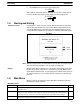
Section 4-4 Saving PT Histories in Files 4-3 Changing File Titles You can change file titles that are already set. 1, 2, 3... 1. 2. 3. 4-4 Go to the File Selection Display. Move the bar cursor to the file for which the title is to be changed, and press F9 (Change Title). An input field will appear for the new title. Input the new title, and then press the Enter Key. Saving PT Histories in Files History information recorded in the PT can be received through the tool interface and saved in a file.
Section 4-5 Setting Initial Screens 3. 4. Input a file name of up to 8 characters, and then press the Enter Key. While the data is being received from the PT, a message will be displayed indicating that history data is being received. When the data has all been received, a message will be displayed. Press any key to return to the File Selection Display.
Section 4-5 Setting Initial Screens 2. Move the bar cursor to the file for which you want to set the initial screen, and then press F8 (Initial Screen). 3. Input the screen number of the initial screen, and then press the Enter Key. (For the NT20M, you can input a screen number from 1 to 250; for the NT600M, from 1 to 1,000.) 4. When the setting has been completed, a message will be displayed. Press any key to return to the File Selection Display.
SECTION 5 Printing This sections describes the procedures for printing screen images and other information from the Screen Selection and File Selection Displays. 5-1 5-2 5-3 Printing Features . . . . . . . . . . . . . . . . . . . . . . . . . . . . . . . . . . . . . . . . . . . . . . . . . . . . . . . . . Printing from the File Selection Display . . . . . . . . . . . . . . . . . . . . . . . . . . . . . . . . . . . . . . . Printing from the Screen Selection Display . . . . . . . . . . . . . . . . . . . . .
Printing from the File Selection Display 5-1 Section 5-2 Printing Features The F3 Function Key can be used from the File Selection Display or the Screen Selection Display to print out actual screens or to print out data related to screens. File Selection Display The following can be printed from the File Selection Display. • File lists: Include file names, memory settings, memory usage, etc. • Screen lists: Includes the screen numbers, comments, and attributes for all screens in a specified file.
Printing from the Screen Selection Display Section 5-3 4. Specify the item to be printed or press the Escape Key to cancel. Printing will start after user confirmation for all items except for screens, in which case the following display will appear. 5. Specify the items to be printed. Printing will start after user confirmation. A message will be displayed during printing and another will appear when printing finishes.
Printing from the Screen Selection Display 3. 104 Section 5-3 Specify the items to be printed. Printing will start after user confirmation. The confirmation screen will show the settings. A message will be displayed during printing and another will appear when printing finishes. The actual image being printed will be displayed when detailed information and screen image are specified.
SECTION 6 Transmitting Data This section describes the procedures to transfer screen and memory table data between the PT and the Support Software. The procedure to delete screens directly from the PT is also provided. 6-1 6-2 6-3 6-4 Connecting to the PT . . . . . . . . . . . . . . . . . . . . . . . . . . . . . . . . . . . . . . . . . . . . . . . . . . . . . . Transmitting Data . . . . . . . . . . . . . . . . . . . . . . . . . . . . . . . . . . . . . . . . . . . . . . . . . . . . . . . . .
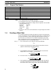
Section 6-2 Transmitting Data 6-1 Connecting to the PT Before beginning transfer operations, connect the computer to the Programmable Terminal according to the system configuration shown below. IBM PC/AT RS-232C 24-VDC power supply 5.25” floppy disk 3.5” floppy disk 100 to 240 VAC 50 Hz/ 60 Hz Note For instructions on the proper connecting cable, refer to the appropriate Programmable Terminal operation manual. 6-2 Transmitting Data Data created with the Support Tool (i.e.
Transmitting Data Section 6-2 Transmitting Files When you transmit a file, screen data, memory table data, and mark data registered in the PT is completely overwritten unless the resume operation is set to ON. If the resume operation is ON, memory table data will not be changed. Note When using EEPROM, the PT memory must be initialized (i.e., cleared) in advance from the maintenance menu to transfer data to the PT’s image data memory. 1, 2, 3... 1. 2. 3. Go to the File Selection Display.
Section 6-2 Transmitting Data 6. Transmitting Screens When the transmission is complete, a message will be displayed. Press any key to return to the File Selection Display. You can transmit single or multiple screens. Note 1. Errors can occur when continuous or overlapping screens are transmitted, so check these screens carefully before sending them. 2. This operation is not possible if EEPROM is used in the PT. Transfer files only. 1, 2, 3... 1. Go the the Screen Selection Display. 2.
Section 6-2 Transmitting Data A message will be displayed asking whether you actually want to transmit the data. The following example shows a case where the tag function is used to designate multiple screens for transmission. 5. 6. 7. To confirm, press the Enter Key. To return to step 1, press any key other than the Enter Key. When the transmission is complete, a message will be displayed. Press any key to return to the Screen Selection Display.
Section 6-3 Receiving Data A message will be displayed asking whether you actually want to transmit the data. 5. 6. 6-3 To confirm, press the Enter Key. To return to step 1, press any key other than the Enter Key. When the transmission is complete, a message will be displayed. Press any key to return to the Screen Selection Display. Receiving Data Data registered in the PT (i.e., screen data, memory table data, and mark data) can be received either by file or by screen (i.e.
Section 6-3 Receiving Data 3. To confirm, press the Enter Key. Press any other key to return to the File Selection Display. 4. Input the name, using up to 8 characters, of the file in which the transmitted data is to be stored, and then press the Enter Key. Input a title of up to 28 characters, and press the Enter Key. When transmission is complete, a message will be displayed. Press any key to return to the File Selection Display. 5. 6.
Section 6-3 Receiving Data 112 3. Select screen data. As the default, “Screen Data” will be displayed in reverse video. To select screen data, just press the Enter Key. 4. Input the number of the screen in the PT that you want the Support Tool to receive, and then press the Enter Key.
Section 6-3 Receiving Data 5. Input the number of the screen where you want the received data to be stored, and then press the Enter Key. A message will be displayed asking whether you actually want to receive the data. 6. To confirm, press the Enter Key. To return to step 1, press any key other than the Enter Key. 7. When the reception is complete, a message will be displayed. Press any key to return to the Screen Selection Display. Note 1.
Section 6-4 Deleting PT Screens 1, 2, 3... 1. 2. 3. Select memory tables and press the Enter Key. A message will be displayed asking whether you actually want to receive the data. 4. To confirm, press the Enter Key. To return to step 1, press any key other than the Enter Key. When the reception is complete, a message will be displayed. Press any key to return to the Screen Selection Display. 5. 6-4 Go to the Screen Selection Display. Press F7 (Receive). The position of the bar cursor is irrelevant.
Section 6-4 Deleting PT Screens 3. Select NT host and, and then press the Enter Key. 4. Input the number of the PT screen to be deleted, and then press the Enter Key. A message will be displayed asking whether you actually want to delete the screen.
Section 6-4 Deleting PT Screens 5. 6. 116 To confirm, press the Enter Key. To abort and return to step 4, press a key other than the Enter Key. When the deletion is complete, a message will be displayed. Press any key to return to the Screen Selection Display.
SECTION 7 PROM Writer Operations This section describes the procedure for transferring screen file data between a PROM writer and the Support Tool. 7-1 7-2 7-3 7-4 Connecting to a PROM Writer . . . . . . . . . . . . . . . . . . . . . . . . . . . . . . . . . . . . . . . . . . . . . . . Transmitting Data to a PROM Writer . . . . . . . . . . . . . . . . . . . . . . . . . . . . . . . . . . . . . . . . . Transmitting Data with Verification to a PROM Writer . . . . . . . . . . . . . . . . . . . . . . . . . . .
Section 7-2 Transmitting Data to a PROM Writer 7-1 Connecting to a PROM Writer Before performing operations, connect an IBM PC/AT and a PROM writer. Use RS-232C interface for data communications with the PROM writer. Set the transmission conditions as shown in the following table. Baud rate 9,600 bps Data length 8 bits Parity None Stop bits 1 Transfer format Intel HEX format IBM PC/AT PROM writer Note 1. Test the PROM Writer in advance to be sure that the PTs’ ROM chip can be written. 2.
Transmitting Data with Verification to a PROM Writer 5. The settings for transfer to the PROM writer will be displayed. Check these settings before transferring the data. 6. After verifying that the PROM writer can receive the data, press the Enter Key. To cancel and return to step 1, press the Escape Key. When the transmission is complete, a message will be displayed. Press any key to return to the Screen Selection Display. 7.
Receiving Data from a PROM Writer 5. The settings for transfer to the PROM writer will be displayed. Check these settings before transferring the data. 6. After verifying that that PROM writer can receive the data, press the Enter Key. To cancel and return to step 3, press the Escape Key. When the transmission is complete, the following message will be displayed and the Support Tool will wait for the data to be sent back from the PROM writer. Transmit the data from the PROM writer.
Receiving Data from a PROM Writer 4. 5. Section 7-4 Input the name, using up to 8 normal characters, of the file in which the data received is to be stored, and then press the Enter Key. Input a title of up to 28 characters, and press the Enter Key. The following message will be displayed and the Support Tool will wait for the data to be sent from the PROM writer. 6. 7. Transmit the data from the PROM writer. When the data has been received, a message will be displayed.
Receiving Data from a PROM Writer Section 7-4 stored up to that point will be cleared.If you wish to overwrite the existing file, press the Enter Key. If you wish to cancel, return to step 1 by pressing a key other than the Enter Key. Then input another name for the new file.
Appendix Special Characters English Character Codes Pin 3 of SW1 must be ON to enable English language messages to use the following codes. Example: Hex code is represented by 30, decimal code by 48, and character by 0. 30 0 48 Code 20 and 32 in the table represents a space, as indicated by “SP”.
Appendix Special Characters Hex Digits 1st 2nd -0 A- A0 B- á D0 E0 176 192 208 224 B1 C1 D1 E1 177 193 209 225 B2 C2 D2 E2 178 194 210 226 B3 C3 D3 E3 179 195 211 227 B4 C4 D4 E4 180 196 212 228 B5 C5 D5 E5 181 197 213 229 B6 C6 D6 E6 182 198 214 230 B7 C7 D7 E7 183 199 215 231 B8 C8 D8 E8 168 184 200 216 232 A9 B9 C9 D9 E9 169 185 201 217 233 AA BA CA DA EA 186 202 218 234 BB CB DB EB 187 203 219 235 BC
Index A-C abbreviations, 2 addresses, data area specifications, 18 alarm, screen attribute, 78 auto refresh, setting, 15 bar graphs, 51 creating direct connection, 55 normal, 52 deleting and modifying, 55 display settings, 54 bit input, screen attribute, 78 buttons, basic operation, 14 buzzer, screen attribute, 78 direct connection bar graphs, 55 conversion, 18 indication on displays, 18 lamps, 43 numeral displays, 31 numeral editing, 63, 68 procedure, 17 setting, 15, 17 touch switches, 48 Unit requirement
Index lamps, 40 creating direct connection, 43 normal, 40 deleting and modifying, 42 labels, 42, 45, 50 lines.
Revision History A manual revision code appears as a suffix to the catalog number on the front cover of the manual. Cat. No. V004-E1-2 Revision code The following table outlines the changes made to the manual during each revision. Page numbers refer to the previous version. Revision code Date 1 September 1991 2 August 1993 Revised content Original production Major revisions for new version of software.