
User's Manual


Model
V680S-HMD66-ETN
2013
RFIDSystemReader/Writer
Observe the following precautions to ensure safe usage of the product.
1.
Installation and Storage Environment
・Do not install the Products near any equipment that generates a large
amount of heat (such as heaters,transformers, and large-capacity
resistors).
・If many Reader/Writer are mounted near each other, communications
performance may decrease due to mutual interference. Refer to
Reference Data in Section 8 Appendices of User’s Manual and check
to make sure there is no mutual interference.
2.
Installation and Removing
・Do not use the AC power supply.
・Do not perform wiring incorrectly. Doing so may result in rupture or
damage from burning.
・Groundto100Ωorlessthroughahostdevice(Ethernetswitch
orPLCsetc).
PRECAUTIONS FOR SAFE USE
1.
Installation and Storage Environment
DonotuseorstoretheProductinthefollowinglocations.
・
Locationssubjecttocorrosivegases,dust,dirt,metalpowder,orsalt.
・Locationswhereambienttemperatureorambienthumidityrange
isoverthespecified.
・Locationssubjecttoextremetemperaturechangesthatmayresult
indewcondensation.
・Locationswheretheproductwouldbedirectlysubjectedto
vibrationorshockexceedingspecifications.
2.
Installation
・TheProductscommunicatewithRFTagsusingthe13.56-MHz
frequency.Anytransceivers,motors,inverters,orswitchingpower
suppliesgeneratenoisethatcanaffectcommunicationswiththe
Tagsandcauseerrors.IfsuchdevicesarelocatedneartheTags,
alwaystestoperationinadvancetoconfirmwhetherthesystem
maybeaffected.
・
WhenyouusetheReader/WriterinRUNmode,thecontrolsignal
shouldbeconnectedtothe+24Vofthepowersupply.The
Reader/Writerwilloperateinsafemodewhenthecontrolsignal
isconnectedto0Vofthepowersupply.
・
MakesurethepowersuppliedbytheDCpowersupplyunitis
withintheratedpowersupplyvoltage(24VDC+10%/−15%)
beforeusingtheProduct.
・
Securely tighten the screws to a torque of 1.2N・m when mounting the
reader/writer.
・
Use a tightening torque of 0.3 to 0.49N・m when mounting the cable connector.
3.
Prohibitions
・
DonotdroptheProducts.
・
Donotpullonthecableswithexcessivestrength.
・Donotattempttodisassemble,repair,ormodifytheProcuct.
4.
Maintenance
・
Thereader/writermustbeinspectedonadailyorregularbasis.
PRECAUTIONS FOR CORRECT USE
©
OMRON Corporation All Rights Reserved.
INSTRUCTION SHEET
Thank you for selecting OMRON product. This sheet pri-
marily describes precautions required in installing and
operating the product.
Before operating the product, read the sheet thoroughly to
acquire sufficient knowledge of the product. For your con-
venience, keep the sheet at your disposal.
OMRON Corporation
Suitability for Use
EUROPE
OMRON EUROPE B.V. Sensor Business Unit
Carl-Benz Str.4, D-71154 Nufringen Germany
Phone:49-7032-811-0 Fax: 49-7032-811-199
NORTH AMERICA
OMRON ELECTRONICS LLC
One Commerce Drive Schaumburg,IL 60173-5302 U.S.A.
Phone:1-847-843-7900 Fax : 1-847-843-7787
ASIA-PACIFIC
OMRON ASIA PACIFIC PTE. LTD.
No. 438A Alexandra Road #05-05-08(Lobby 2),
Alexandra Technopark, Singapore 119967
Phone : 65-6835-3011 Fax :65-6835-2711
o
THE PRODUCTS CONTAI NED IN THIS SHEET ARE NOT SAFETY RATED.
THEY ARE NOT DESIGNED OR RATED FOR ENSURING SAFETY OF
PERSONS, AND SHOULD NOT BE RELIED UPON AS A SAFETY
COMPONENT OR PROTECTIVE DEVICE FOR SUCH PURPOSES.
Please refer to separate catalogs for OMRON's safety rated products.
OMRON shall not be responsible for conformity with any standards, codes, or
regulations that apply to the combination of the products in the customer's
application or use of the product.
Take all necessary steps to determine the suitability of the product for the
systems, machines, and equipment with which it will be used.
Know and observe all prohibitions of use applicable to this product.
NEVER USE THE PRODUCTS FOR AN APPLICATION I
NVOLVING
SERIOUS RISK TO LIFE OR PROPERTY WITHOUT ENSURING THAT THE
SYSTEM AS A WHOLE HAS BEEN DESIGNED TO ADDRESS THE RISKS,
AND THAT THE OMRON PRODUCT IS PROPERLY RATED AND
INSTALLED FOR THE INTENDED USE WITHIN THE OVERALL
EQUIPMENT OR SYSTEM.
See also Product catalog for Warranty and Limitation of Liability.
CHINA
OMRON(CHINA) CO., LTD.
Room 2211, Bank of China Tower,
200 Yin Cheng Zhong Road,
PuDong New Area, Shanghai, 200120, China
Phone : 86-21-5037-2222 Fax :86-21-5037-2200
OCT, 2009
D
Manufacturer:
Omron Corporation,
Shiokoji Horikawa, Shimogyo-ku,
Kyoto 600-8530 JAPAN
Ayabe Factory
3-2 Narutani, Nakayama-cho,
Ayabe-shi, Kyoto 623-0105 JAPAN
TRACEABILITY INFORMATION:
Representative in EU:
Omron Europe B.V.
Wegalaan 67-69
2132 JD Hoofddorp,
The Netherlands
Item
Specifications
Supply voltage 24 VDC (-15% to +10%)
Consumption surrent
0.2A max.
Ambient operating
temperature
Insulation resistance
20MΩ min.(with 500 VDC megohmmeter)
Between cable terminals and casing
Dielectric strengh 1000VAC,50/60Hz,1min
Between cable terminals and casing
Vibration resistanse
10 to 500 Hz, double amplitude: 1.5 mm,
Max. Acceleration: 100m/s
2
, with 10 sweeps for 11 min.
each in 3 directions
Shock resistance
Dimensions
Degree of protection
IP67 (IEC 60529)
Oil resistance equivalent to IP67F (JIS C 0920:2003, Appendix 1)
Material Case: PBT resin, Filled resin: Urethane resin
Mass
Mounting method
M4 screws
Please use more than 12 mm of the screw length.
Ambient operating
humidity
25 to 85%RH(No dew condensation)
Host communication
interface
EtherNet 10/100BASE-T
1. Rating performance
Ambient storage
temperature
-25 to 70℃(No freezing.)
Ambient storage
humidity
25 to 85%RH(No dew condensation)
Host communication
protocol
MODBUS TCP
Accessory
Approx. 630 g
120 × 120 × 40 mm (excluding protruding parts)
-10 to 55℃(No freezing.)
Instruction Seet: 1 sheet
Description of Regulations and Standard: 1 sheet
IP Address label: 1 sheet
Ferrite core: 1 piece
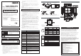
4. Dimensions
3. Part Names and functions
2. Installation
Connector
NORM/ERR
LINK/ACT
RUN
RF
NORM/ERR
NORM/ERR
NORM/ERR
(2)Status indicators
RUN
RF
Flashing green
green
yellow
ColorName
green
Flash while the Reader/Writer is operating in Safe mode.
Lighting while the Reader/Writer is operating normally.
Lighting during communication for RF Tag.
Description
Lighting when the communications finish with no error.
red
Lighting once when an error occurs during communications
with the host device, or during communications with an RF Tag.
Lighting when unrecoverable error occurs.
Flashing red
Flash when recoverable error occurs.
(Configuration memory error, or Control signal wiring mistake, etc.)
LINK/ACT
green
Lighting during linking normaly.
NORM/ERR
Flashing green
Flash during detects a carrier.
Attaching Reader/Writer to the cable
1. Hold the cable connector, and insert the
cable connector into the Reader/Writer
connector.
2. Turn the threaded portion of the cable
connector clockwise to lock it in place.
Recommended tightening torque: 0.39 to 0.49 N・m
(1)Connector
The connector is used to connect the
exclusivecableas
modelV680S-A40,
V680S-A41,orV680S-A42
.
1
2
3
4
5
6
7
8
1
2
3
4
5
FG
TD-
CONT
24P
RD+
Name
PIN No.
6
7
8
TD+
RD-
24N
Frame ground
Ethernet send data -
Control signal
+24V
Ethernet receive data +
Function
Ethernet send data +
Ethernet receive data -
0V
(Drain wire)
Orange
Purple
Brown
Green/White
(stripe)
Orange/White
(stripe)
Green
Blue
-
-
Purple
Brown
-
The color of the
wiring of the
V680S-A41.
-
-
Blue
The color of the
wiring of the
V680S-A42.
SAFETY PRECATIONS
Meaning of Signal Words
Warning
WARNING
TheseProductsarenotdesignedtobeusedeitherdirectly
orindirectlyinapplicationsthatdetecthumanpresencefor
thepurposeofmaintainingsafety.Donotusethese
Productsasasensingmeansforprotectinghumanlives.
InIndicatesapotentiallyhazardoussituation
which,ifnotavoided,willresultinminoror
moderateinjury,ormayresultinseriousinjury
ordeath.Additionally,theremaybesignificant
propertydamage.
WARNING
Meaning of Alert Symbols
Indicatesgeneralprohibitionsforwhichthereisno
specificsymbol.
・UseanexclusivecableasmodelV680S-A40,V680S-A41,or
V680S-A42.
3.
Using
・Donotbendthecablepastabendingradiusof40mm.Thecable
maybedisconnected.
・Ifyoufindanabnormaloperationoftheproduct,immediatelystop
itsoperationandturnOFFthepowersupply.Consultwithan
OMRONrepresentative.
4.
Cleaning
・
DonotcleantheProductswithpaintthinner,benzene,acetone,orkerosene.
5.
Disposing
・DisposeoftheProductsasindustrialwaste.
Mount the Reader/Writer with four M4 screws with spring washers and flat washers
as shown above. Recommended tightening torque: 1.2 N
・m
M4 screw
Spring washer
Flat washer
110±0.2
110±0.2
Four, M4
Mounting Hole Dimensions
17.5
Connector
60
31
120
110
Four, 4.5-dia.
mounting holes
120
110
(16)
136
40
4.9
6
Seven, Operation indicators
Standards label
Nameplate
M12 threaded section
(Unit : mm)
Mechanical durability: 500m/s
2
, 3times each in 6 directions
Not lit
Turn off when power is not supplied.
Not lit
Turn off when not in communication with the RF tags.
Not lit
Turn off when the standby state.
Not lit
Turn off when the ethernet cable is not connected.