Spain Tel: +34 913 777 900 www.omron.es Belgium Tel: +32 (0) 2 466 24 80 www.omron.be Germany Tel: +49 (0) 2173 680 00 www.omron.de Norway Tel: +47 (0) 22 65 75 00 www.omron.no Sweden Tel: +46 (0) 8 632 35 00 www.omron.se Czech Republic Tel: +420 234 602 602 www.omron.cz Hungary Tel: +36 (0) 1 399 30 50 www.omron.hu Poland Tel: +48 (0) 22 645 78 60 www.omron.com.pl Switzerland Tel: +41 (0) 41 748 13 13 www.omron.ch Denmark Tel: +45 43 44 00 11 www.omron.dk Italy Tel: +39 02 32 681 www.omron.
F7Z Quick Start Guide Table of Contents Warnings ...................................................................... EN-2 Safety Precautions and Instructions ........................................................................... EN-3 EMC Compatibility ...................................................................................................... EN-4 Installation .................................................................... EN-6 Mechanical Installation .........................
Warnings CAUTION Cables must not be connected or disconnected, nor signal tests carried out, while the power is switched on. The Varispeed F7 DC bus capacitor remains charged even after the power has been switched off. To avoid an electric shock hazard, disconnect the frequency inverter from the mains before carrying out maintenance. Then wait for at least 5 minutes after all LEDs have gone out. Do not perform a withstand voltage test on any part of the Varispeed.
Safety Precautions and Instructions General Please read these safety precautions and instructions for use thoroughly before installing and operating this inverter. Also read all of the warning signs on the inverter and ensure they are never damaged or removed. Live and hot inverter components may be accessible during operation. Removal of housing components, the digital operator or terminal covers runs the risk of serious injuries or damage in the event of incorrect installation or operation.
Electrical Connection Carry out any work on live equipment in compliance with the national safety and accident prevention regulations. Carry out electrical installation in compliance with the relevant regulations. In particular, follow the installation instructions ensuring electromagnetic compatibility (EMC), e.g. shielding, grounding, filter arrangement and laying of cables. This also applies to equipment with the CE mark.
Laying Cables Measures Against Line-Borne Interference: Line filter and frequency inverter must be mounted on the same metal plate. Mount the two components as close to each other as possible, with cables kept as short as possible. Use a power cable with well-grounded shield. For motor cables up to 50 meters in length use shielded cables. Arrange all grounds so as to maximize the area of the end of the lead in contact with the ground terminal (e.g. metal plate).
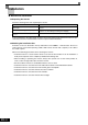
Installation Mechanical Installation Unpacking the Inverter Check the following items after unpacking the inverter. Item Has the correct Inverter model been delivered? Is the Inverter damaged in any way? Are any screws or other components loose? Method Check the model number on the nameplate on the side of the Inverter. Inspect the entire exterior of the Inverter to see if there are any scratches or other damage resulting from shipping. Use a screwdriver or other tools to check for tightness.
Installation Orientation Install the Inverter vertically so as not to reduce the cooling effect. When installing the Inverter, always provide the following installation space to allow normal heat dissipation. A B Air A B 200V class inverter, 0.55 to 90 kW 50 mm 120 mm 400V class inverter, 0.55 to 132 kW 200V class inverter, 110 kW 120 mm 120 mm 400V class inverter, 160 to 220 kW 400V class inverter, 300 kW 300 mm 300 mm 50mm min. 30mm min. 30mm min. 120mm min.
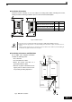
Electrical Connection Wiring the Inverter DC reactor to improve input power factor (optional) Braking resistor unit (optional) Short-circuit bar Main Contactor 2 T B1 1 B2 Fuses 3-phase power L1 380 to 480 V L2 50/60 Hz Line Filter L3 R/L1 U/T1 S/L2 T/L3 W/T3 Varispeed F7 PE Multi-function digital inputs [Factory setting] M V/T2 Forward Run / Stop S1 Reverse Run / Stop S2 MB External Fault S3 MC Fault reset S4 Multi-step speed setting 1 S5 Multi-step speed setting 2 S6
Main Circuit Terminals Main circuit terminal functions are summarized according to terminal symbols in Table 1. Wire the terminals correctly for the desired purposes.
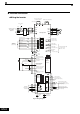
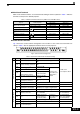
Type No. M1 Digital output signals M2 Signal Name Function During run (NO) Closed during Run Zero speed (NO) Closed when output frequency at zero level (b2-01) or below M3 M4 M5 M6 Speed agreement detection (NO) Signal Level Function selected by H2- Relay contacts 01 to H2-03 Contact capacity: 1 A max. at 250 VAC Within ± 2 Hz of set fre1 A max.
Sinking/Sourcing Mode (NPN/PNP Selection) The input terminal logic can be switched over between sinking mode (0-V common, NPN) and sourcing mode (+24V common, PNP) by using the jumper CN5. An external power supply is also supported, providing more freedom in signal input methods.
Wiring Main Circuit Inputs Installing Fuses To protect the inverter, it is recommended to use semiconductor fuses like they are shown in the table below. Table 4 Input Fuse Selection 20P4 20P7 21P5 22P2 23P7 25P5 27P5 2011 2015 2018 2022 2030 2037 2045 2055 2075 2090 2110 Rated Inverter Output Current (A) 3.2 4.1 7.0 9.6 15 23 31 45 58 71 85 115 145 180 215 283 346 415 40P4 40P7 41P5 42P2 43P7 44P0 45P5 47P5 4011 4015 4018 4022 4030 4037 4045 4055 4075 4090 4110 4132 1.8 2.1 3.7 5.3 7.6 8.7 12.
• If an earth leakage breaker is used, it should be able to detect all kinds of current in order to ensure a safe earth leakage current detection • A magnetic contactor or other switching device can be used at the inverter input. The inverter should not be powered up more than once per hour. • The input phases (R/S/T) can be connected in any sequence.
Keypad Operation Digital Operator Display (optional) The key names and functions of the Digital Operator are described below Drive Mode Indicators FWD: Lights up when a forward run command is input. REV: Lights up when a reverse run command is input. SEQ: Lights up when any other run command source than the Digital Operator is selected. REF: Lights up when any other frequency reference source than the Digital Operator is selected. ALARM: Lights up when an error or alarm has occurred.
Power Up and Basic Parameter Setup Start Up Procedure START Installation Wiring Set power supply voltage jumper *1 Turn ON power Confirm status Select control method. Basic settings (Quick programming mode) NO V/f control Vector Control (A1-02 = 2 or 3) *5 YES YES PG? V/f Control with PG (A1-02 = 1 NO V/f control Set E1-03. V/f default: 200V/50Hz (400V/50Hz) Set E1-03, E2-04 and F1-01.
Before Power Up The following points should be checked carefully before the power is switched on. • Check if the power supply meets the inverter specification. • Check if the power supply cables are tightly connected to the right terminals (L1, L2, L3). • Check if the motor cables are tightly connected to the right terminals on the inverter side (U, V, W) as well as on the motor side. • Check if the braking unit / braking resistor is connected correctly.
motor parameters will be set automatically. The remaining motor parameters will be set automatically during the first time operation. Non-rotating Autotuning for Line-to-Line Resistance (T1-01 = 2) Non-rotating autotuning for line-to-line resistance can be used in any control mode. This is the only possible autotuning for V/f control and V/f control with PG.
User Parameter Parameter Number Name Description A1-01 A1-02 A1-03 Language selection for Digital Operator display(JVOP160-OY only) 0:English 2: German 3: French 4: Italian 5: Spanish 6: Portuguese Parameter access level 0:Monitoring only (Monitoring drive mode and setting A1-01 and A1-04.) 1: Used to select user parameters (Only parameters set in A2-01 to A2-32 can be read and set.) 2: Advanced (Parameters can be read and set in both, quick programming mode (Q) and advanced programming mode (A).
Parameter Number Name Max. output E1-04 frequency (FMAX) Description H3-13 Frequency (Hz) E1-13 Base Voltage (VBASE) To set V/f characteristics in a straight line, set the same values for E1-07 and E1-09. In this case, the setting for E1-08 will be disregarded.
Parameter Number Name Parameter Number Description Forward drive torque limit Reverse drive L7-02 torque limit Sets the torque limit vlaue as a percentage of the motor rated torque. Four individual regions can be set. Output torque Positive torque Forward L7-03 regenerative torque limit Reverse No. o motor rotations Regen. Regen.
Troubleshooting General Faults and Alarms Faults and Alarms indicate unsusal inverter / application conditions. An alarm does not necessarily switch off the inverter but a message is displayed on the keypad (i.e. a flashing alarm code) and an alarm output can be generated at the multi-function outputs (H2-01 and H2-02) if programmed. An alarm automatically disappears if the alarm condition is not present anymore.
Display Alarm OC Over Current Fault OH Heatsnk Overtemp OH1 Heatsink Max Temp Meaning Corrective Actions • Remove the motor and run the Inverter without the motor. • Check the motor for a phase-to-phase Over Current The Inverter’s output current exceeded the over- short. • Verify the accel/decel times (C1-). current detection level. • Check the Inverter for a phase-to-phase short at the output.
Alarm Display Fault PUF DC Bus Fuse Open RR DynBrk Transistr (only in UV1 stop DC Bus Undervolt conditio) UV2 CTL PS Undervolt Meaning Corrective Actions • Check the motor and the motor cables for DC Bus Fuse Open short circuits or insulation failures (phaseThe fuse in the main circuit is blown. to-phase). Warning: PG (encoder) pulses have not been received for • Replace the inverter after correcting the fault. a time longer than the setting in F1-14.
Display Meaning Corrective Actions Function Selection Error A setting has been made that is applicable with the curOPE08 Verify the control method and the function. rent control method. Constant Selection Example: A function used only with open loop vector control was selected for V/f control. OPE010 V/f Ptrn Setting Check parameters (E1-). A frequency/voltage value may be set higher than the maximum frequency/voltage. V/f Parameter Setting Error Autotuning Faults Autotuning faults are shown below.