Cat. No. Z209-E1-01 Smart Sensor Multi-Controller ZS-MDC (Ver 2.0) ZS-MDC Smart Sensors Multi-Controller OMRON Corporation Industrial Automation Company Application Sensors Division Sensing Devices and Components Division H.Q. Shiokoji Horikawa, Shimogyo-ku, Kyoto, 600-8530 Japan Tel: (81)75-344-7068/Fax: (81)75-344-7107 Regional Headquarters OMRON EUROPE B.V. Sensor Business Unit, Carl-Benz-Str.
Introduction This manual provides information regarding functions, performance and operating methods that are required for using the ZS-MDC. When using the ZS-MDC, be sure to observe the following: • The ZS-MDC must be operated by personnel knowledgeable in electrical engineering. • To ensure correct use, please read this manual thoroughly to deepen your understanding of the product. • Please keep this manual in a safe place so that it can be referred to whenever necessary.
SECTION 1 FEATURES SECTION 2 INSTALLATION & CONNECTION SECTION 3 SETUP SECTION 4 APPLICATION SETTING EXAMPLES SECTION 5 APPENDIX Section User's Manual Smart Sensors Multi-Controller ZS-MDC Introduction ‚Í‚¶‚ß‚É Section ‘æ 1 Í 1 Section ‘æ 2 Í 2 Section ‘æ 3 Í 3 Section ‘æ 4 Í 4 Section 5 INTRODUCTION APPLICATION CONSIDERATIONS (Please Read)
Introduction Introduction READ AND UNDERSTAND THIS DOCUMENT Please read and understand this document before using the products. Please consult your OMRON representative if you have any questions or comments. WARRANTY OMRON’s exclusive warranty is that the products are free from defects in materials and workmanship for a period of one year (or other period if specified) from date of sale by OMRON.
Introduction THE PRODUCTS CONTAINED IN THIS DOCUMENT ARE NOT SAFETY RATED. THEY ARE NOT DESIGNED OR RATED FOR ENSURING SAFETY OF PERSONS, AND SHOULD NOT BE RELIED UPON AS A SAFETY COMPONENT OR PROTECTIVE DEVICE FOR SUCH PURPOSES. Please refer to separate catalogs for OMRON’s safety rated products.
Introduction Introduction DIMENSIONS AND WEIGHTS Dimensions and weights are nominal and are not to be used for manufacturing purposes, even when tolerances are shown. ERRORS AND OMISSIONS The information in this document has been carefully checked and is believed to be accurate; however, no responsibility is assumed for clerical, typographical, or proofreading errors, or omissions.
Introduction Precautions for Safe Use Introduction Precautions for Safe Use Please observe the following precautions for safe use of the products. (1) Installation Environment • Do not use the product in environments where it can be exposed to inflammable/ explosive gas. • To secure the safety of operation and maintenance, do not install the product close to high-voltage devices and power devices. (2) Power Supply and Wiring • The supply voltage must be within the rated range (DC24V±10%).
Introduction Precautions for Correct Use Introduction Precautions for Correct Use Please observe the following precautions to prevent failure to operate, malfunctions, or undesirable effects on product performance.
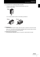
Introduction Precautions for Correct Use Introduction (3) Orientation when Installing the Multi-Controller To improve heat radiation, install the Multi-Controller only in the orientation shown below. Right Do not install the Multi-Controller in the following orientations. Wrong Wrong (4) Warming Up After turning ON the power supply, allow the product to stand for at least 30 minutes before use.
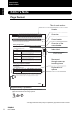
Introduction Editor's Note Introduction Editor's Note Page Format Title of each section Header Overview Section 3 Setting the Sensor Controller to Obtain Sensing Information from Cross-header Setting the Sensor Controller to Obtain Sensing Information from Set which gang-mounted Sensor Controller to obtain information from, and which logic operations are to be performed on that information. Overview of the cross-header Setting Assignments Assign the channel to perform logic operation on.
Introduction Editor's Note Menu items that are displayed on the Multi-Controller LCD screen, and windows, dialog boxes and other GUI elements displayed on the PC are indicated enclosed by brackets [aa]. Introduction ■ Meaning of Symbols ■ Visual Aids Indicates points that are important to ensure full product performance, such as operational precautions and application procedures. Indicates pages where related information can be found. Indicates information helpful in operation.
Introduction Editor's Note Introduction 10 MEMO ZS-MDC User’s Manual
Introduction Contents Precautions for Safe Use 5 Precautions for Correct Use 6 Editor's Note 8 Page Format 8 Contents 11 Section 1 FEATURES 1-1 Multi-Controller Features 1-2 Multi-Controller Applications 1-4 Basic Configuration 1-7 Part Names and Functions 1-8 Section 2 INSTALLATION & CONNECTION 2-1 About Installation and Connection 2-2 Multi-Controller 2-3 Attaching the ferrite core 2-3 Installing the Multi-Controller 2-4 About the I/O cable 2-10 Section 3 SETUP 3-1 Setti
Introduction Contents Introduction 12 Section 4 APPLICATION SETTING EXAMPLES 4-1 Measuring the Thickness of Multiple Points (sandwiched thickness) 4-2 Measuring the Relative Difference between Steps 4-5 Measuring the Reference Difference between Steps 4-8 Measuring Flatness 4-10 Measuring the Average Height 4-12 Measuring the Twist of a Workpiece 4-14 Measuring the Warp of a Workpiece 4-17 Section 5 APPENDIX 5-1 Troubleshooting 5-2 Error Messages and Countermeasures 5-3 Q&A 5-4 Glo
Section 1 FEATURES Section 1 FEATURES Multi-Controller Features 1-2 Multi-Controller Applications 1-4 Basic Configuration 1-7 Part Names and Functions 1-8 ZS-MDC User’s Manual 1-1
Section 1 Multi-Controller Features Multi-Controller Features Section 1 FEATURES The Multi-Controller is a dedicated controller that gets and performs logical operations on data obtained from multiple Sensor Controllers. This Multi-Controller features completely digital-based, data corruption-free logic operation capabilities, and outstanding operability and convenience.
Section 1 Multi-Controller Features (4) Same Compact Size as Sensor Controller • The Multi-Controller is the same compact size as the Sensor Controller, which means that it can be installed at a wide range of sites. • A wide range of processing functions (e.g. filter and hold) the same as those on a Sensor Controller are incorporated on the Multi-Controller, enabling processing of logic operations matched to specific applications. List of Setup Items p.
Section 1 Multi-Controller Applications Multi-Controller Applications Section 1 FEATURES 1-4 ● Measurement of Workpiece Thickness at Multiple Locations Sensor Heads can be placed so as to sandwich the workpiece and measure its thickness. Logic operations can be performed not only on one location but on multiple locations to calculate the difference in the measurement result.
Section 1 Multi-Controller Applications Measurement of Workpiece Flatness Logic operations can be performed on measured values obtained from multiple Sensor Controllers to measure the flatness of workpieces. ● Measurement of Workpiece Strain Logic operations can be performed on measured values obtained from multiple Sensor Controllers to measure the waviness, flexure, twist, and warp of steel plate and other workpieces.
Section 1 Multi-Controller Applications Moreover, connecting a personal computer pre-installed with SmartMonitor Zero to the Multi-Controller allows you to perform the following. Section 1 FEATURES ● Gang-mounted Sensor Controllers can be set up. The measurement conditions of each Sensor Controller can be set up, and settings saved, read or copied. * The screen shown here may differ from the actual screen. ● The state of gang-mounted Sensor Controllers can be monitored.
Section 1 Basic Configuration Basic Configuration Sensor Heads Sensor Controllers Multi-Controller ZS-MDC11/MDC41 The Multi-Controller calculates the measurement information of gang-mounted Sensor Controllers, and outputs the calculation results. This section detects the sensing object and processes measurement. Up to 9 Sensor Controllers can be gang-mounted. For details, refer to the User's Manual for the Sensor Controller.
Section 1 Part Names and Functions Part Names and Functions Section 1 FEATURES The following describes the names and functions of parts on the Multi-Controller.
Section 1 Part Names and Functions (7) Control keys The Control Keys are for setting measurement conditions and other information. The functions assigned to the Control Keys change according to the operating mode. (8) Mode Switch The Mode Switch selects the operating mode. RUN mode : Select this mode when performing regular measurement. TEACH mode : Select this mode when setting the judgment thresholds. FUN mode : Select this mode when setting measurement conditions.
Section 1 Part Names and Functions MEMO Section 1 FEATURES 1-10 ZS-MDC User’s Manual
Section 2 INSTALLATION & CONNECTION 2-2 Multi-Controller 2-3 Attaching the ferrite core 2-3 Installing the Multi-Controller 2-4 About the I/O cable 2-10 ZS-MDC User’s Manual Section 2 INSTALLATION & CONNECTION About Installation and Connection 2-1
Section 2 About Installation and Connection About Installation and Connection ■ Checking the installation environment Read “Precautions for Safe Use” at the beginning of this manual, and check the installation environment. Section 2 INSTALLATION & CONNECTION 2-2 ■ Checking the installation site Read “Precautions for Correct Use” at the beginning of this manual, and check the installation site. ■ About the power supply Before installing and connecting the Multi-Controller, be sure to turn it OFF.
Section 2 Multi-Controller Multi-Controller This section describes installation of the Multi-Controller and connection of the I/O cable. Before connecting/disconnecting peripheral devices, make sure that the Multi-Controller is turned OFF. The Multi-Controller may break down if the Multi-Controller is connected or disconnected while the Attaching the ferrite core Attach the ferrite core (provided with the Multi-Controller) to the I/O cable of the MultiController.
Section 2 Multi-Controller Installing the Multi-Controller The Multi-Controller performs logical operations on the sensing information obtained from multiple connected Sensor Controllers. Up to 9 Sensor Controllers can be gang-mounted. For details on the Sensor Controller and Sensor Heads, refer to the User's Manual for the Sensor Controller. Section 2 INSTALLATION & CONNECTION Provide power to all connected Sensor Controllers. ■ About channel No.
Section 2 Multi-Controller ■ Installing on the DIN track The following describes how to attach the 35 mm wide DIN track by quick, easy operation. End plate (sold separately) PFP-M ● Installation procedure The following describes how to install the Multi-Controller and Sensor Controller on the DIN track. 1. Hook the connector end of the Sensor Section 2 INSTALLATION & CONNECTION DIN track (sold separately) PFP-100N (1 m) PFP-50N (0.5 m) PFP-100N2 (1 m) Controller onto the DIN track.
Section 2 Multi-Controller 3. Open the connector cover on the controller. LD H ON P Controller Link Unit (sold separately) ZE RO L EN AB LE Slide the cover to remove. LD H P ON ZE L 4. EN AB LE Insert the Controller Link Unit into the Section 2 INSTALLATION & CONNECTION connector on the Multi-Controller. The connectors are designed to be connected in a particular direction.
Section 2 Multi-Controller 4. Pull the hook on the I/O cable end downwards. 5. Lift up the Sensor Controller from the I/O Hook on I/O cable Section 2 INSTALLATION & CONNECTION cable end, and remove it from the DIN track.
Section 2 Multi-Controller ■ Mounting on a panel The optional Panel Mount Adapters (ZS-XPM1/XPM2) can be used to mount the MultiController on a panel. Panel Mount Adapters p.5-9 Section 2 INSTALLATION & CONNECTION 1. Install the Multi-Controller and Sensor Controller on the DIN track. p.2-5 When mounting on a panel, be sure to install the DIN track on the rear side of the MultiController for support. 2.
Section 2 Multi-Controller 4. Install the long Mount Adapters on the Panel Mount Adapter two holes on the small Mount Adapter. H LD P ON ZE RO L EN AB LE Install the long Mount Adapters only on both LD H ON P ZE RO L EN AB LE sides of gang-mounted controllers. ON P ZE RO L EN AB LE Section 2 INSTALLATION & CONNECTION 5. LD H Panel Mount Adapter Install the Multi-Controller and Sensor Controller with Panel Mount Adapters Panel attached onto the panel from the front.
Section 2 About the I/O cable About the I/O cable ■ Wiring the I/O cable The following shows the leads that comprise the I/O cable. Brown Blue Section 2 INSTALLATION & CONNECTION Red Green Black Pink Gray Co-axial (black) Shielded Yellow Light blue Purple White Orange (1) (1) Power supply (2) GND (3) OUT0 (4) OUT1 (5) OUT2 (6) OUT3 (7) OUT4 (8) Linear output (9) Linear GND (10) IN0 (11) IN1 (12) IN2 (13) IN3 (14) Unused Power supply This connects the 24 VDC (±10%) power supply.
Section 2 About the I/O cable (6) OUT3 (ENABLE output) This turns ON when the Multi-Controller is ready for measurement. This output is interlocked with the ENABLE indicator. (7) OUT4 (BUSY output) (8) Linear output The linear output outputs a current or voltage in accordance with the measured value. (9) Linear GND The linear GND terminal is the 0V terminal for the linear output. This ground wire must be grounded separately from the other ground wires.
Section 2 About the I/O cable ■ I/O Circuit Diagrams ● NPN type (ZS-MDC11) Brown DC24V Red OUT0 Green OUT1 Load Load Black OUT2 Pink OUT3 Gray OUT4 Load Load DC24V Blue GND(0V) Internal circuits Section 2 INSTALLATION & CONNECTION Load Yellow IN0 Light blue IN1 Purple IN2 White IN3 Orange Current output 4 to 20 mA Current voltage/ output selector switch 40 Ω Co-axial (black) Linear output Voltage output 10 V Load Shielded 2-12 ZS-MDC User’s Manual Linear GND Current output: 300
Section 2 About the I/O cable PNP type (ZS-MDC41) Brown DC24V Red OUT0 Green OUT1 Load Black OUT2 Pink OUT3 Gray OUT4 Section 2 INSTALLATION & CONNECTION Load Load DC 24V Load Load Blue GND(0V) Yellow Internal circuits ● IN0 Light blue IN1 Purple IN2 White IN3 Orange Current output 4 to 20 mA Current voltage/ output selector switch 40Ω Co-axial (black) Linear output Voltage output 10 V Load Shielded Current output: 300 Ω or less Voltage output: 10 kΩ or more Linear GND ZS-MDC User’s
Section 2 About the I/O cable MEMO Section 2 INSTALLATION & CONNECTION 2-14 ZS-MDC User’s Manual
Section 3 SETUP Setting Flow 3-2 About Setup 3-4 List of Setting Items Selecting Tasks 3-4 3-9 3-13 Setting the Sensor Controller to Obtain Sensing Information from 3-14 Setting Assignments 3-14 Setting Logic Operation Methods 3-15 Setting I/O Assignments Section 3 SETUP Basic Knowledge for Operation 3-16 Switching banks by external signal input 3-16 Changing Output Assignments 3-17 Changing Linear Output Assignments 3-17 About Digital Output 3-17 ZS-MDC User’s Manual 3-1
Section 3 Setting Flow Preparation for Measurement Setting Flow Installation and Connection Gang-mount Sensor Controller to Multicontroller. Section 2 Installation & Connection p.2-2 Section 3 SETUP Setting of Measurement Conditions Power ON Setting the Sensor Controller to obtain sensing information from Set the Sensor Controller to obtain sensing information from and operations to be performed. Setting Filter Function Set the filter conditions for processing measured information.
Section 3 Setting Flow When a Problem Occurs... The Multi-Controller does not operate correctly. Troubleshooting p.5-2 An error message has appeared When [Error] is Displayed on the Main Display p.5-3 Section 3 SETUP Want to know the meanings of terms Additional Functions Applied Use of Functions Glossary p.5-5 Setting Banks Set up the banks. Sensor Controller User's Manual, Section 3 Setup Set Up the System Environment Set up the system environment.
Section 3 About Setup About Setup The ZS-MDC Series can be set up on the Multi-Controller or on the SmartMonitor Zero software utility. This manual describes setup on the Multi-Controller. For details on how to set up the ZS-L Series on SmartMonitor Zero, refer to Help contained on the SmartMonitor Zero CD-ROM. Section 3 SETUP Basic Knowledge for Operation The following describes basic operation of the Multi-Controller before you set up the ZS-L Series.
Section 3 About Setup ■ Displays and Key Operations The Multi-Controller has digital displays and an LCD screen.The details displayed on these differ according to the operating mode. Main Display Sub-display LCD screen Alphabet characters that appear on the digital displays Section 3 SETUP Control keys (1) FUN Mode The LCD screen displays the setup menus. The No. at the top of each menu corresponds to a function key.
Section 3 About Setup Key FUN Mode ↑ UP key ↓ DOWN key Changes numerical values during numerical value input. MENU key Displays the top menu of the FUN mode. SET key Applies the item you are setting up. ESC key Returns to the previous menu. Section 3 SETUP The following example describes basic operations for changing the filter to [SMOOTH]. 1. Press function key 2 representing [FILTER]. 2. Press function key 1 representing [SMOOTH]. The currently selected No. is displayed flashing. 3.
Section 3 About Setup ● RUN Mode In this mode, measured values are displayed on the main display, and threshold values and other information are displayed on the sub-display. Pressing the MENU key displays the display customize menu.
Section 3 About Setup Key Section 3 SETUP ● Measured Value Display Display Customize Menu ↑ UP key ↓ DOWN key ↑ UP key: Executes trigger input. The function changes depend↓ DOWN key: Executes reset ing on the settings. input. • Changes numerical values. • Changes text. MENU key Displays the display customize menu. Returns to the top of the display customize menu. SET key Executes a zero reset. Applies numerical value settings. ESC key Hold down for at least two seconds to cancel a zero reset.
Section 3 About Setup List of Setting Items This manual describes only “FUN Mode-[SENSING]” functions unique to the Multi-Controller. Details of other functions are the same as those for the Sensor Controller. Refer to the Sensor Controller Userís Manual. ■ FUN Mode ● When TASK1 is selected FUN Mode Settings SENSING FILTER OUTPUT HOLD 0RESET Default Value Option/Range Pages SEL CH - Input A to input I CALC CH OFF, CH (input A to input I), CALC p.
Section 3 About Setup Settings I/O SET JUDGE ANALOG INPUT Section 3 SETUP I/O SET BANK SYSTEM Default Value COM (RS-232C) COM 3-10 ZS-MDC User’s Manual Pages NO-MEAS CLAMP KEEP, CLAMP - HYS 20 µm 0 to 999.
Section 3 About Setup ● When other than TASK1 is selected FUN Mode Settings SENSING FILTER HOLD 0RESET Page s Option/Range CALC CH OFF, CH(input A to input I), CALC (THICK, STEP, K+mX+nY, AVE, MAX-MIN) p.
Section 3 About Setup ■ RUN Mode In the RUN mode, you can customize the details that are displayed in the digital displays. To call the display customize menu, press the MENU key in the RUN mode. RUN mode DIGITAL LCD Settings Default Value Option/Range Page s Section 3 SETUP DOT 3 0 to 5 - ECO NORMAL NORMAL, ECO, OFF - ON/OFF ON ON, AUTOOFF, OFF - B.
Section 3 Selecting Tasks Selecting Tasks By assigning expressions to “tasks,” you can process (multi-tasking) multiple logic operations (max. 4). After selecting the task in the task selection menu, make the various settings for the selected task in the respective setup menus. The currently selected task is displayed on the sub-display. Press the ESC key with the FUN Mode-TOP menu displayed. Setting Description Selects TASK1 as the destination to store the expression to.
Section 3 Setting the Sensor Controller to Obtain Sensing Information from Setting the Sensor Controller to Obtain Sensing Information from Set which gang-mounted Sensor Controller to obtain information from, and which logic operations are to be performed on that information. Setting Assignments Assign the channel to perform logic operation on. ▲ Section 3 SETUP 3-14 FUNMode-[SENSING]-[SEL CH] Setting Description INPUT A (input A) Assigns the target Sensor Controller to input A.
Section 3 Setting the Sensor Controller to Obtain Sensing Information from Setting Logic Operation Methods Set how logic operations are to be performed on the tasks and CH specified by the assignment settings. ▲ FUNMODE-[SENSING]-[CALC] Setting Description OFF Expressions are not set. CH Logic operations are not performed, and the measured value of a specific CH is input as it is.Select the target CH. THICK K-(X+Y) Select this item to set the sandwiched thickness.
Section 3 Setting I/O Assignments Setting I/O Assignments Switching banks by external signal input Set the task or function to the external input. If you use SmartMonitor Zero, you can change the function assignments of IN2 and IN3 if [BANK] is selected. For details, refer to the Help for SmartMonitor Zero. ▲ Section 3 SETUP FUN mode-[I/O SET]-[I/O SET]-[IN] Setting TASK FUNC Description Select to task for enabling the external signal lead.
Section 3 Setting I/O Assignments Changing Output Assignments ▲ FUN mode-[I/O SET]-[I/O SET]-[OUT] Setting TASK1 TASK2 TASK3 TASK4 Description The measurement value of the task selected here is output as the judgment result of the Multi-Controller. ▲ FUN Mode-[I/O SET]-[I/O SET]-[ANALOG] Setting TASK1 TASK2 TASK3 TASK4 Description The measurement value of the task selected here is linear-output from the MultiController.
Section 3 Setting I/O Assignments MEMO Section 3 SETUP 3-18 ZS-MDC User’s Manual
Section 4 APPLICATION SETTING EXAMPLES Measuring the Thickness of Multiple Points (sandwiched thickness)4-2 4-5 Measuring the Reference Difference between Steps 4-8 Measuring Flatness 4-10 Measuring the Average Height 4-12 Measuring the Twist of a Workpiece 4-14 Measuring the Warp of a Workpiece 4-17 ZS-MDC User’s Manual Section 4 APPLICATION SETTING EXAMPLES Measuring the Relative Difference between Steps 4-1
Section 4 Measuring the Thickness of Multiple Points (sandwiched thickness) Measuring the Thickness of Multiple Points (sandwiched thickness) This is an example of how to measure the sandwiched thickness at three places on a workpiece, and calculate the difference (max. value - min. value) of each measured thickness value. [THICK] and [MAX-MIN] are used as the operation modes.
Section 4 Measuring the Thickness of Multiple Points (sandwiched thickness) ▲ Press MENU key - ESC key. 2. Select [TASK1]. 1 TASK1 3 TASK3 2 TASK2 4 TASK4 ▲ [SENSING]-[CALC]-[CALC]-[THICK] 3. Set the expression of TASK1. 2 INPUT Y 1 INPUT X 3 THICK INPUT Y: INPUT B 4. Input A Place a workpiece of known thickness at the X rough sensor. 5. Y Select [THICK]. Input B 6. Enter the thickness of the workpiece. The thickness of the workpiece you placed is THICK DIG : VAL 010.
Section 4 Measuring the Thickness of Multiple Points (sandwiched thickness) ▲ Press MENU key - ESC key. 9. To set the expression for calculating the difference in the thickness of the 3 locations for TASK4, select [TASK4]. 1 TASK1 3 TASK3 2 TASK2 4 TASK4 ▲ [SENSING]-[CALC]-[CALC]-[MAX-MIN] 10.
Section 4 Measuring the Relative Difference between Steps Measuring the Relative Difference between Steps This is an example of how to measure the height at three locations on a workpiece, and calculate the difference (step difference) between each of the measured values. Use [STEP] (X-Y) for the expression. Input A Input B Input C Step difference Step difference Step difference CH1 CH2 CH3 The operation and/or measurement results are output as judgement output or linear output.
Section 4 Measuring the Relative Difference between Steps ▲ [SENSING]-[CALC]-[CALC]-[STEP] 3. Set the expression of TASK1. 1 INPUT X INPUT X: INPUT A 2 INPUT Y Input A Input B Input C INPUT Y: INPUT B Y X 4. Following the same procedure as 2 to 3, set up TASK2. Input B Input C Y INPUT Y: INPUT C 5. Following the same procedure as 2 to 3, set Input A up TASK3. INPUT X: INPUT C Input B X Y INPUT Y: INPUT A • To output the judgment result of the operation [I/O SET]-[I/O SET]-[OUT] 6.
Section 4 Measuring the Relative Difference between Steps ▲ • To linear-output the operation result [I/O SET]-[I/O SET]-[ANALOG] 6. Select TASK1, TASK2, or TASK3 depending on the details to be output.
Section 4 Measuring the Reference Difference between Steps Measuring the Reference Difference between Steps This is an example of how to measure the height at three locations on a workpiece, and calculate the difference (step difference) between the value of the reference height (obtained by taking one of the locations to be the reference height) and the other two locations. Use [STEP] (X-Y) for the expression.
Section 4 Measuring the Reference Difference between Steps ▲ [SENSING]-[CALC]-[CALC]-[STEP] 3. Set the expression of TASK1. 1 INPUT X INPUT X: INPUT A Input A 2 INPUT Y Input B Input C INPUT Y: INPUT B Y X 4. Following the same procedure as 2 to 3, set Input A up TASK2. Input C Y X INPUT Y: INPUT C ▲ • To output the judgment result of the operation [I/O SET]-[I/O SET]-[OUT] 5. Select TASK1 or TASK2 depending on the details to be output.
Section 4 Measuring Flatness Measuring Flatness This is an example of how to measure the height at 9 locations on a workpiece, and calculate the difference (max. value - min. value) between each measured point. [MAXMIN] is used as the operation mode. Input A Input B Input I Input C Input A Input B Input C The operation and/or measurement results are output as judgement output or linear output.
Section 4 Measuring Flatness ▲ Press MENU key - ESC key. 2. Select [TASK1]. 1 TASK1 3 TASK3 2 TASK2 4 TASK4 ▲ [SENSING]-[CALC]-[CALC]-[MAX-MIN] 3. Set input A to input I for calculating the flatness to ON, and other input to OFF. 2 INPUT B 1 TASK1 3 TASK3 2 TASK2 4 TASK4 1 TASK1 3 TASK3 2 TASK2 4 TASK4 ▲ • To output the judgment result of the operation [I/O SET]-[I/O SET]-[OUT] 4. Select [TASK1] so that the judgment on the flatness measurement can be output.
Section 4 Measuring the Average Height Measuring the Average Height This is an example of how to measure the height at 3 locations on a workpiece, and calculate the average of each measured height value. [AVERAGE] is used as the operation mode. Input A Input B Input C Input A Input B Input C The operation and/or measurement results are output as judgement output or linear output. For details on how to connect and install the Sensor Heads and Sensor Controllers, refer to the “ZS-L User’s Manual”.
Section 4 Measuring the Average Height ▲ [SENSING]-[CALC]-[CALC]-[AVE] 3. Set input A to input C for calculating the average to ON, and other inputs to OFF. 1 INPUT A 3INPUT C 2INPUT B 1 TASK1 3 TASK3 2 TASK2 4 TASK4 1 TASK1 3 TASK3 2 TASK2 4 TASK4 ▲ • To output the judgment result of the operation [I/O SET]-[I/O SET]-[OUT] 4. Select [TASK1] so that the judgment on the average value can be output. 4. Select [TASK1] so that the average value can be linear-output.
Section 4 Measuring the Twist of a Workpiece Measuring the Twist of a Workpiece This is an example of how to measure the height at 4 locations on a workpiece, and calculate the difference (twist) between each of the measured values. Use [X-Y] for the expression. Input A Input B Input D Input C CH0 CH1 CH2 CH3 CH4 The operation and/or measurement results are output as judgement output or linear output.
Section 4 Measuring the Twist of a Workpiece ▲ Press MENU key - ESC key. 2. Select [TASK1]. 1 TASK1 3 TASK3 2 TASK2 4 TASK4 ▲ [SENSING]-[CALC]-[CALC]-[STEP] 3. Set the expression of TASK1. 1 INPUT X 2 INPUT Y Input A Input D INPUT Y: INPUT B Input B 4. Input C Following the same procedure as 2 to 3, set Input A up TASK2. Input B Input D Input C INPUT X: INPUT D INPUT Y: INPUT C 5. Following the same procedure as 2 to 3, set Input A Input D up TASK2.
Section 4 Measuring the Twist of a Workpiece ▲ • To output the judgment result of the operation [I/O SET]-[I/O SET]-[OUT] 6. Select [TASK3] so that the judgment on the twist can be output. 1 TASK1 3 TASK3 2 TASK2 4 TASK4 1 TASK1 3 TASK3 2 TASK2 4 TASK4 ▲ • To linear-output the operation result [I/O SET]-[I/O SET]-[ANALOG] 6. Select [TASK3] so that the twist value can be linear-output.
Section 4 Measuring the Warp of a Workpiece Measuring the Warp of a Workpiece In the example below, the difference between the points on both edges (input A point and input C point) of the workpiece, the average distance value, and the measured value (input B point) of the center is taken to be the warp amount. Expression: Z=B- (A+C)/2. In the actual setting, calculation mode “K+mX+nY” is used.
Section 4 Measuring the Warp of a Workpiece ▲ Press MENU key - ESC key. 2. Select [TASK1]. 1 TASK1 3 TASK3 2 TASK2 4 TASK4 ▲ [SENSING]-[CALC]-[CALC]-[K+mX+nY] 3. Section 4 APPLICATION SETTING EXAMPLES 4-18 Set the expression of TASK1. INPUT K:0 1 INPUT A 3 INPUT C 2 INPUT B Input A Input B INPUT m:1 Input C INPUT n:1 INPUT X: INPUT A INPUT Y: INPUT C 4. Following the same procedure as 2 to 3, set up TASK2. INPUT K:0 INPUT m:1 INPUT n:-0.
Section 4 Measuring the Warp of a Workpiece ▲ • To output the judgment result of the operation [I/O SET]-[I/O SET]-[OUT] 5. Select [TASK2] so that the judgment on the warp can be output. 1 TASK1 3 TASK3 2 TASK2 4 TASK4 1 TASK1 3 TASK3 2 TASK2 4 TASK4 ▲ • To linear-output the operation result [I/O SET]-[I/O SET]-[ANALOG] 5. Select [TASK2] so that the warp value can be linear-output.
Section 4 Measuring the Warp of a Workpiece MEMO Section 4 APPLICATION SETTING EXAMPLES 4-20 ZS-MDC User’s Manual
Section 5 APPENDIX 5-2 Error Messages and Countermeasures 5-3 Q&A 5-4 Glossary 5-5 Specifications and External Dimensions 5-6 Version Up Information 5-12 INDEX 5-13 Revision History 5-16 ZS-MDC User’s Manual Section 5 APPENDIX Troubleshooting 5-1
Section 5 Troubleshooting Troubleshooting This section describes countermeasures for temporary hardware problems. Check the malfunction in this section before sending the hardware for repair. Problem Section 5 APPENDIX 5-2 Probable cause and possible countermeasure Pages Device restarts during operation. • Is the power supply device connected correctly? p.2-10 Judgments are not output to external device.
Section 5 Error Messages and Countermeasures Error Messages and Countermeasures ■ When [Error] Is Displayed on the Main Display Display Details LCD screen (upper section) Cause Countermeasure Overcurrent One or all of the judgment out- Cancel the load short-circuit. puts are short-circuited. (Recovery is automatic after the load short-circuit is canceled.
Section 5 Q&A Q&A Question When scaling is executed, an error appears and settings cannot be made. Scaling cannot be set for one of the following reasons: • Scaling has been attempted when the measured value is outside the measuring range. • When two-point scaling has been executed, the distance between the measured values for the two points is not 1% or more of the rated measuring range. When focusing is executed, an error appears and settings cannot be made.
Section 5 Glossary Glossary Term Measured value Explanation The measured value is the operation result displayed on the main display of the Multi-Controller in the RUN and TEACH modes. It is the value when each of the currently set functions (e.g. hold) has been processed. p.3-7 Present value The present value is the current measurement result for the target Multi-Controller. It is the value before each of the currently set functions (e.g. hold) has been processed.
Section 5 Specifications and External Dimensions Specifications and External Dimensions Multi-Controller ZS-MDC11/MDC41 (Unit: mm) 52.50 60 4.3 3.90 90 Section 5 APPENDIX 10.80 5-6 ZS-MDC User’s Manual 32.90 24.
Section 5 Specifications and External Dimensions Item I/O type ZS-MDC11 NPNtype ZS-MDC41 PNPtype No. of samples to average 1, 2, 4, 8, 16, 32, 64, 128, 256, 512, 1024, 2048, or 4096 Number of mounted Sensor Heads Cannot be connected Connectable version of Sensor Controller Ver2.0 or later Number of mounted Sensor Controllers Max. 9 (The Controller Link Unit is needed for gang-mounting.) Exte Connection method rnal I/F Serial I/O USB2.
Section 5 Specifications and External Dimensions Item ZS-MDC41 300 m/s2 3 times each in six directions (up/down, left/right, forward/ backward) Ambient temperature Operating: 0 to 50°C Storage: -15 to +60°C (with no icing or condensation) Ambient humidity Operating and storage: 35% to 85% RH (with no condensation) Materials Case: Polycarbonate (PC) Weight Approx.
Section 5 Specifications and External Dimensions Panel Mount Adapters ZS-XPM1/XPM2 When mounting on a panel (60 n)+12 60 n Panel (Unit: mm) 13 3 (140) 90 122 DIN track Panel Panel Mount Adapter Note 1) 116 1 Panel Panel cutout cutout dimensions dimensions Section 5 APPENDIX Note 1: Dimensions are shown for a panel thickness of 2.0 mm.
Section 5 Specifications and External Dimensions RS-232C Cable for Connecting to a Personal Computer ZS-XRS2 2000 (Unit: mm) 150 41 32.20 4 5.20 80 10-pin square connector 8.70 20 5 9-pin p square q connector PVC insulated round cable 3.89 mm dia. core ((conductor cross-section: 0.013 mm2/insulator diameter: 0.38)) Note 1: Connector is socket type. 1 2 3 4 5 Fitting 10 1 Section 5 APPENDIX 6 7 NC Pin No. 1 Pin No.
Section 5 Specifications and External Dimensions Controller Link Unit ZS-XCN (Unit: mm) 39.50 Item Applicable controller 4.60 Section 5 APPENDIX 13.40 11.50 18 ZS-XCN ZS Series Ambient temperature Operating: 0 to 50°C, Storage: -15 to +60°C (with no icing or condensation) Ambient humidity Operating and storage: 35% to 85% RH (with no condensation) Vibration resistance 10 to 150 Hz, 0.
Section 5 Version Up Information Version Up Information This section describes the revisions made to the software. ■ Ver1.00 to Ver1.50 Description of Change Task setup function was added. Pages p.3-13 Logic operation can be performed on the information of Sensor Controllers up to nine channels. p.3-14 “K+mX+nY” that enables average height measurement and flexible formulas on types of logic operations were added. p.3-15 The zero reset memory function was added.
Section 5 Index Index LCD screen name LD ON LOG LOW indicator Output A Bank switching Basic Configuration BUSY output 3-16 1-7 2-11 CALC Control keys Controller Link Unit Connection Specifications and Dimensions Coupler 3-15 3-5 DIGITAL 3-17 ENABLE indicator Output Extension Cable 1-8 2-11 5-11 3-15 B Main Display Mode Switch Multi-Controller Attaching the ferrite core Installation Part Names Specifications and Dimensions 2-5 D OUT OUT0 to 4 Output cable 1-9 2-10 2-10 2-13 3-16, 3-17 3-14
Section 5 Index U USB port 1-9 V Voltage/Current switch 1-9 W wiring 2-10 Z Zero reset indicator Section 5 APPENDIX 5-14 ZS-MDC User’s Manual 1-8
Section 5 Index MEMO Section 5 APPENDIX ZS-MDC User’s Manual 5-15
Revision History Revision History A manual revision code appears as a suffix to the catalog number at the bottom of the front and back covers of this manual. Cat. No.
Terms and Conditions of Sale 1. Offer; Acceptance. These terms and conditions (these "Terms") are deemed part of all quotes, agreements, purchase orders, acknowledgments, price lists, catalogs, manuals, brochures and other documents, whether electronic or in writing, relating to the sale of products or services (collectively, the "Products") by Omron Electronics LLC and its subsidiary companies (“Omron”).
OMRON ELECTRONICS LLC 1 Commerce Drive Schaumburg, IL 60173 847.843.7900 For US technical support or other inquiries: 800.556.6766 OMRON CANADA, INC. 885 Milner Avenue Toronto, Ontario M1B 5V8 416.286.6465 OMRON ON-LINE Global - http://www.omron.com USA - http://www.omron.com/oei Canada - http://www.omron.ca Z209-E1-01 11/05 ©2005 OMRON ELECTRONICS LLC Printed in the U.S.A. Specifications subject to change without notice.