
Installation Manual

2) Attach an RG6 "F" connector to the cable. Connect to fitting on module and finger tighten.
C. Satellite Connection
1) Identify cables from the satellite antenna and receiver
outlets and route to appropriate fitting. In routing cable,
allow slack for bundling cables to the side. Trim cable to
allow a loose loop of cable to the connection.
2) Attach an RG6 "F" connector to the cable. Connect to
fitting on module and finger tighten.
D. Auxiliary Input Connections (if applicable)
1) Identify cables for auxiliary inputs and route to appropriate
fitting. In routing cable, allow slack for bundling cables to
the side. Trim cable to allow a loose loop of cable to the
connection.
2) Attach an RG6 "F" connector to the cable. Connect to fitting
on module and finger tighten.
E. Outlet Drop Connections
1) Identify cables from the outlets and route to appropriate
fittings. In routing cables, allow slack for bundling cables to the
side. Trim cable to allow a loose loop of cable to the
connection.
2) Attach an RG6 "F" connector to the cable.
3) Remove terminator from fitting and connect cable to module and finger
tighten.
4) Place terminator on outlet after installation.
Note: Cables should all be marked to provide identification. Record room locations for cables
from outlets and auxiliary inputs.
F. Power Connection (if applicable)
1) Identify amplifier power cables and route to appropriate fitting. In routing cable, allow slack for
bundling cables to the side. Trim cable to allow a loose loop of cable to the connection.
2) Attach an RG6 "F" connector to the cable. Connect to fitting on module and finger tighten.
3) Attach an RG6 "F" connector to the opposite end of the cable. Connect to the amplifier
transformer provided with module.
4) Plug transformer into a standard 110 VAC outlet.
Warning: Damaged cable from the transformer may be hazardous and should be replaced.
Caution: Do not connect power to any other device or fitting. Connecting to other fittings may damage
attached products.
Note: No field serviceable parts inside module.
Disclaimer
OnQ recommends using RG-6 quad shielded solid copper cable in lieu of copper clad steel, especially with
applications that involve distributing DC voltages. Solid copper offers less DC resistance than copper clad
steel and thus less of a voltage drop. Many manufactures of 3rd party devices such as satellite receivers' state
NOT to use copper clad steel for this reason. Use of copper clad steel could result in voltage drop significant
enough to interfere with a DC voltage dependant device's operation. As in any RF or RF/DC application, try to
avoid excessively long runs.
OnQ Technologies, Inc.
P.O. Box 60907
Harrisburg, PA 17106-0907
800-321-2343
www.onqtech.com
Installation/Instruction Sheet
OnQ Video Modules
IS-0013 Rev. E
IS-0013 Rev. E Page 2 of 2
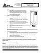
Figure 3