
Datasheet

1N53 Series
http://onsemi.com
6
100
10
1
0.1
80 100 120 140 160 180 200 220
V
Z
, ZENER VOLTAGE (VOLTS)
I
Z
, ZENER CURRENT (mA)
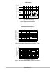
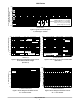
Figure 9. Zener Voltage versus Zener Current
V
Z
= 82 thru 200 Volts
APPLICATION NOTE
Since the actual voltage available from a given Zener
diode is temperature dependent, it is necessary to determine
junction temperature under any set of operating conditions
in order to calculate its value. The following procedure is
recommended:
Lead Temperature, T
L
, should be determined from:
T
L
= q
LA
P
D
+ T
A
q
LA
is the lead-to-ambient thermal resistance and P
D
is the
power dissipation.
Junction Temperature, T
J
, may be found from:
T
J
= T
L
+ DT
JL
DT
JL
is the increase in junction temperature above the lead
temperature and may be found from Figure 4 for a train of
power pulses or from Figure 1 for dc power.
DT
JL
= q
JL
P
D
For worst-case design, using expected limits of I
Z
, limits
of P
D
and the extremes of T
J
(DT
J
) may be estimated.
Changes in voltage, V
Z
, can then be found from:
DV = q
VZ
DT
J
q
VZ
, the Zener voltage temperature coefficient, is found
from Figures 2 and 3.
Under high power-pulse operation, the Zener voltage will
vary with time and may also be affected significantly by the
zener resistance. For best regulation, keep current
excursions as low as possible.
Data of Figure 4 should not be used to compute surge
capability. Surge limitations are given in Figure 5. They are
lower than would be expected by considering only junction
temperature, as current crowding effects cause temperatures
to be extremely high in small spots resulting in device
degradation should the limits of Figure 5 be exceeded.