
Data Sheet


© 2011 Fairchild Semiconductor Corporation www.fairchildsemi.com
FDMF6823A • Rev. 1.0.3 14
FDMF6823A — Extra-Small, High-Performance, High-Frequency DrMOS Module
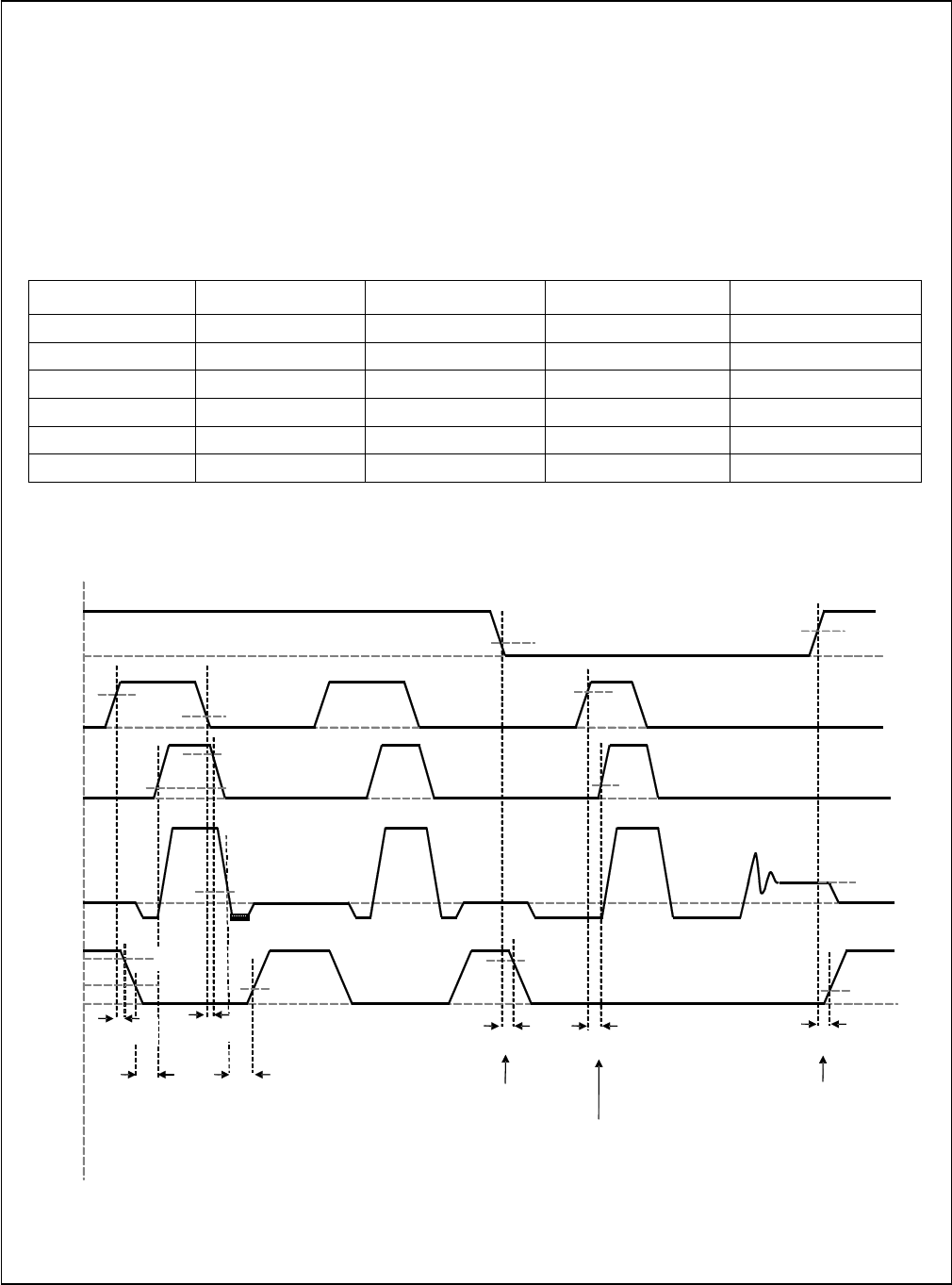
Skip Mode (SMOD#)
The Skip Mode function allows for higher converter
efficiency when operated in light-load conditions. When
SMOD# is pulled LOW, the low-side MOSFET gate
signal is disabled (held LOW), preventing discharge of
the output capacitors as the filter inductor current
attempts reverse current flow – known as “Diode
Emulation” Mode.
When the SMOD# pin is pulled HIGH, the synchronous
buck converter works in Synchronous Mode. This mode
allows for gating on the Low Side MOSFET. When the
SMOD# pin is pulled LOW, the low-side MOSFET is
gated off. If the SMOD# pin is connected to the PWM
controller, the controller can actively enable or disable
SMOD# when the controller detects light-load condition
from output current sensing. Normally this pin is active
LOW. See Figure 28 for timing delays.
Table 2. SMOD# Logic
DISB# PWM SMOD# GH GL
0 X X 0 0
1 3-State X 0 0
1 0 0 0 0
1 1 0 1 0
1 0 1 0 1
1 1 1 1 0
Note:
4. The SMOD# feature is intended to have a short propagation delay between the SMOD# signal and the low-side
FET V
GS
response time to control diode emulation on a cycle-by-cycle basis.
Figure 28. SMOD# Timing Diagram
t
D_DEADON
PWM
V
SWH
GH
to
V
SWH
GL
t
PD_PHGLL
t
PD_PLGHL
t
D_DEADOFF
V
IH_PWM
V
IL_PWM
90%
10%
90%
1.0V
2.2V
t
PD_PHGHH
t
PD_SHGLH
Delay from SMOD# going
HIGH to LS V
GS
HIGH
HS turn -on with SMOD# LOW
SMOD
#
t
PD_SLGLL
Delay from SMOD# going
LOW to LS V
GS
LOW
DCM
CCM
CCM
10%
V
IH_PWM
10%
V
OUT
V
IH_SMOD
V
IL_SMOD
10%