
Data Sheet

KA3842B/KA3843B/KA3844B/KA3845B
5
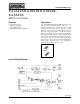
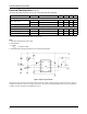
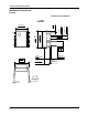
Figure 2. Under Voltage Lockout
During Under-Voltage Lock-Out, the output driver is biased to a high impedance state. Pin 6 should be shunted to ground with
a bleeder resistor to prevent activating the power switch with output leakage current.
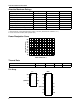
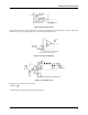
Figure 3. Error Amp Configuration
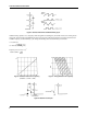
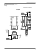
Figure 4. Current Sense Circuit
Peak current (I
S
) is determined by the formula:
A small RC filter may be required to suppress switch transients.
I
S
MAX()
1.0V
R
S
------------=