
Data Sheet


KA3842B/KA3843B/KA3844B/KA3845B
6
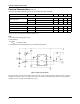
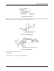
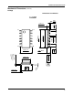
Figure 5. Oscillator Waveforms and Maximum Duty Cycle
Oscillator timing capacitor, C
T
, is charged by V
REF
through R
T
and discharged by an internal current source. During the dis-
charge time, the internal clock signal blanks the output to the low state. Selection of R
T
and C
T
therefore determines both
oscillator frequency and maximum duty cycle. Charge and discharge times are determined by the formulas:
t
c
= 0.55 R
T
C
T
Frequency, then, is: f=(t
c
+ t
d
)
-1
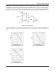
Figure 8. Shutdown Techniques
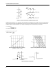
Figure 6. Oscillator Dead Time & Frequency Figure 7. Timing Resistance vs Frequency
t
D
R
T
C
T
I
n
0.0063R
T
2.7–
0.0063R
T
4–
----------------------------------------
=
ForRT 5KΩ f
1.8
R
T
C
T
---------------=,>
(Deadtime vs C
T
RT > 5kΩ)