Sanitary Water Heat Pump ‐ Operation and Installation Manual - AXHW-20a/200L;AXHW-20a/250L;AXHW-20a/300L
TABLE OF CONTENT INTRODUCTION........................................................................................................................................................2 This manual.........................................................................................................................................................2 The unit...........................................................................................................................................................
INTRODUCTION This manual This manual includes the necessary information about the unit. Please read this manual carefully before you use and maintain the unit. The unit The hot water heat pump is one of the most economical systems to heat the water for family domestic use. Using free renewable energy from the air, the unit is highly efficient with low running costs. Its efficiency can be up to 3 ~ 4 times more than conventional gas boilers or electrical heaters.
Multiple Functions The special design of the air inlet and outlet makes the unit suitable for various ways of connections. With different ways of installation, the unit can work as just a heat pump but also as a fresh air blower, a dehumidifier, or an energy recovery device. Other features Stainless steel tank and a magnesium stick assure the durability of components and the tank. Highly efficient compressor with the R134a refrigerant.
Be sure to use the provided or specified parts for the installation work. The use of defective parts could cause an injury due to possible fire, electric shocks, the unit falling etc. Perform the installation securely and please refer to the installation instructions. Incorrect installation could cause an injury due to possible fire, electric shocks, the unit falling, leakage of water etc. Perform electrical work according to the installation manual and be sure to use a dedicated section, fused with 16A.
Caution Do not install the unit in a place where there is a chance of flammable gas leaks. If there is a gas leak and gas accumulates in the area surrounding the unit, it could cause an explosion. Perform the drainage/piping work according to the installation instruction. If there is a defect in the drainage/piping work, water could leak from the unit and household goods could get wet and be damaged. Do not clean the unit when the power is ‘ON’.
ITEMS INSIDE PRODUCT BOX Before starting the installation, please make sure that all parts are found inside the box.
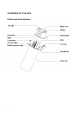
OVERVIEW OF THE UNIT Parts and descriptions 7
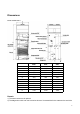
Dimensions Model: AXHW-20a/*** A B D E F G H J K L M N 200L Φ560 Φ177 1185 875 1750 450 1025 600 250 32.5 35 1135 250L Φ640 Φ177 1070 790 1633 450 890 550 250 32.5 35 1020 300L Φ640 Φ177 1280 1030 1845 450 1130 680 250 32.5 35 1230 Remark: 1) The extra heat source is optional. 2) The Magnesium stick is an anti-corrosion element.
creation of fur around the inside tank and to protect the tank, and other components. It can help to extend the life-span of the tank. Check the magnesium stick every half year and change it if it has been used out! How to replace the magnesium stick - : Turn the power of the unit ‘OFF’ and pull out the plug. Drain all the water out of the tank. Remove the old magnesium stick from the tank. Replace the new magnesium stick. Recharge the water.
INSTALLATION Asked your supplier to install the unit. Incomplete installation performed by yourself may result in a water leakage, electric shock, or fire. Indoor installation is highly recommended. It is not allow to install the unit at outdoor or rain achieving place. The installation place without direct sunlight and other heat supplies is recommended. If no way to avoid these, please install a covering. The unit must be securely fixed to avoid noise and shaking.
Required service space Below you will find the minimum space required to be able to complete service and maintenance tasks on the units. Note: - 11 If air inlet and/or outlet pipes are connected, portion airflow and capacity in heat pump unit will lose. If the unit connects with air ducts it should be DN 180mm for pipes or 180mm internal diameter flexible hose. Total length of the ducts should not be longer than 8m or the maximum static pressure should not exceed than 60Pa.
Installation overview Note: Solar heat exchange coil is optional. ATTENTION: - The one-way safety valve must be installed. If not, it could cause damage to the unit, or even hurt people. The set point of this safety valve is 0.7 MPa. For the installation place please refer to the pipeline connection sketch. - The discharge pipe connected to the one-way safety valve is to be installed in a continuously downward direction and in a frost-free environment.
- The water may drip from the discharge pipe of the one-way safety valve and that this pipe must be left open to the atmosphere. - The one-way safety valve is to be operated regularly to remove lime deposits and to verify that it is not blocked. Please beware of burn, because of the high temperature of water. - The tank water can be drained through the drainage hole on the bottom of the tank. - After all the pipes installed turn on the cold water inlet and hot water outlet to fill the tank.
Installation positions (1) Waste heat can be useful heat Units can be installed near the kitchen, in the boiler-room or the garage, basically in every room which has a large number of waste-heat so that the unit has the higher energy efficiency even with very low outside temperatures during the winter. (2) Hot water and dehumidification Units can be placed in the laundry room or clothing room. When it produces hot water it lowers the temperature and dehumidifies the room as well.
Water loop connection Please pay attention to the below points when connecting the water loop pipe: 1. Try to reduce the water loop resistance 2. Make sure there is nothing in the pipe and the water loop is smooth, check the pipe carefully to see if there is any leak, and then pack the pipe with the insulation. 3. Install the one way valve and safety valve in the water circulation system. 4.
Wire connection • • • • The specification of the power supply wire is 3*1.5 mm². Fuse specification is T 3.15A 250V There must be a switch when connecting the unit to the power system. The current of the switch is 10A. The unit must be installed a Creepage Breaker near the power supply and must be effectively earthed. The specification of the creepage breaker is 30mA, less than 0.1sec. THE APPLIANCE SHALL BE INSTALLED IN ACCORDANCE WITH NATIONAL WIRING REGULATIONS.
OPERATION THE UNIT User interface and operation Electrical heater ‘ON’/’OFF’ button Unit ‘ON’/’OFF’ button UP adjust button Set button Clock/Timer setting button DOWN adjust button Operations 1. Power ‘ON’ When turning ‘ON’ the power, whole icons are displayed on the controller screen for 3 seconds. After checking if everything is ok, the unit enters into the standby mode. 2. 17 button Press this button and keep for 2 seconds when the unit is standby, the unit can be turned ‘ON’.
3. ‐ ‐ ‐ ‐ ‐ ‐ 4. And buttons These are the multi-purpose buttons. They are used for the temp setting, parameter setting, parameter checking, clock adjustment and adjustment of the timer. or button to adjust the setting temperature directly. During running status, press Press these buttons when the unit is on clock setting status, the hour(s) and the minute(s) of the clock time can be adjusted.
NOTE: 1) The timer ‘ON’ and timer ‘OFF’ functions can be set at the same time. 2) The timer settings are repeating. 3) The timer settings are still valid after a sudden power cut. 6. button 1) When the heat pump is ON, press this button to turn ‘ON’ the electrical heater. The heater will be showed, and the electrical heater will work according to the control program icon (parameter 3). 2) When the heat pump is ON, press this button and hold for 5 seconds to enable or disable the fan ventilation function.
LED icons 1. Hot water available The icon indicates that the domestic hot water temperature reaches the set point. The hot water is available for use. Heat pump is standby. 2. Fan ventilation The icon indicates that the fan ventilation function is enabled. button and hold it for 5 seconds the fan ventilation function When the unit is on, press the can be enabled or disabled.
8. Right temperature display The display shows the current downside temperature of the water tank. When checking or adjusting the parameters, this section will display the related parameter value. In case any malfunction occurs, this section will display the related error code. 9. Time display The display shows the clock time or timer time. 10. Timer ‘ON’ The icon indicates that the timer ‘ON’ function is enabled. 11. Timer ‘OFF’ The icon indicates that the timer ‘OFF’ function is enabled. 12.
PARAMETER CHECKING AND ADUSTMENT Parameter list Some parameters can be checked and adjusted by the controller. Below is the parameter list. Parameter Description Range Default Remarks No. 0 Tank water setting temp. 10 ~ 70°C 50°C Adjustable Inlet/Outlet water temp 1 2 ~ 15°C 5°C Adjustable difference 2 3 4 5 6 7 8 9 10 11 12 13 A E-heater off tank water temp E-heater delay time Week disinfection temperature High temp disinfection time Defrosting period Defrosting entry coil temp.
Malfunctioning of the unit and error codes When an error occurs or the protection mode is set automatically, the circuit board and the wired controller will both display the error message. Protection/ Malfunction Standby Normal running Lower tank water temp. sensor failure Upper tank water temp. sensor failure Evaporator coil temp. sensor failure Return air temp sensor failure Ambient temp.
Protection/ Malfunction Error code EE2 Low pressure protection (LP Switch) EE3 Over heat protection (HTP Switch) Defrost Communica tion failure Defro sting indica te EE8 LED indicator Possible reasons Corrective actions 1) Too low air inlet temp 2) The electronic expansion valve assembly blocked ☆☆☆☆☆ 3) Too less refrigerant ☆☆● (7 flashes 1 4) The switch damaged dark) 5) The fan assembly can not work 1) Check if the air inlet temp is over the working limited 2) Replace the electronic expansion v
MAINTENANCE Maintenance activities In order to ensure an optimum operation of the unit, a number of checks and inspections on the unit and the field wiring have to be carried out at regular intervals, preferably yearly. Check the water supply and air vent frequently, to avoid lack of water or air in the water loop. Clean the water filter to keep a good water quality. Lack of water and dirty water can damage the unit. Keep the unit in a place where it is dry and clean, and which has good ventilation.
TROUBLESHOOTING This section provides useful information for diagnosing and correcting certain troubles which may occur. Before starting the troubleshooting procedure, carry out a thorough visual inspection of the unit and look for obvious defects such as loose connections or defective wiring. Before contacting your local dealer, read this chapter carefully, it will save you time and money.
WIRING DIAGRAM Please refer to the wiring diagram on the electric box.
TECHNICAL SPECIFICATION AXHW-20a/*** TECHNICAL DATA (AXHW-20a/***) Power supply V/Ph/Hz Water tank Volume L Max power input W Max current A Max.outlet water °C temperature range(without using E-heater) Max. water temperature °C Min. water temperature °C Ambient working temp. °C Max. discharge pressure bar Min.
Net Dimensions Packing Dimensions Net Weight mm mm φ560x1750 φ640x1633 φ640x1845 615x615x1870 695x695x1753 695x695x1965 Kg 90 94 344 98 46 97 Weight with full water Kg 290 Gross Weight Kg 94 Noise level dB (A) 46 NOTES: * During disinfection, the max water temp could be up to 70°C by electrical heater 29 397 101 46
TEMPERATURE SENSOR R-T CONVERSION TABLE R25= ℃ 5.0KΩ±1.0% Rmin /KΩ B25-50 = 3470K±1.0% KΩ Rmax/ KΩ ℃ Rmin KΩ /KΩ -20 -19 -18 -17 -16 -15 -14 -13 -12 -11 -10 -9 -8 -7 -6 -5 -4 -3 -2 -1 0 1 2 3 4 5 6 7 8 9 10 11 12 13 14 15 16 17 18 19 20 36.195 34.402 32.709 31.109 29.597 28.168 26.816 25.538 24.328 23.183 22.098 21.071 20.098 19.176 18.301 17.472 16.686 15.94 15.231 14.559 13.92 13.313 12.736 12.188 11.666 11.17 10.698 10.249 9.822 9.414 9.027 8.657 8.305 7.969 7.648 7.343 7.051 6.773 6.507 6.