TELEDYNE HASTINGS INSTRUMENTS INSTRUCTION MANUAL HFM-300 FLOW METER, HFC-302 FLOW CONTROLLER
Manual Print History The print history shown below lists the printing dates of all revisions and addenda created for this manual. The revision level letter increases alphabetically as the manual undergoes subsequent updates. Addenda, which are released between revisions, contain important change information that the user should incorporate immediately into the manual. Addenda are numbered sequentially.
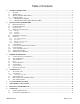
Table of Contents 1. GENERAL INFORMATION............................................................................................................................................ 4 1.1. FEATURES .................................................................................................................................................................... 4 1.2. SPECIFICATIONS ...............................................................................................................................
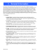
1. General Information The Teledyne Hastings HFM-300 is used to measure mass flow rates in gases. In addition to flow rate measurement, the HFC-302 includes a proportional valve to accurately control gas flow. The Hastings mass flow meter (HFM-300) and controller (HFC-302), hereafter referred to as the Hastings 300 series, are intrinsically linear and are designed to accurately measure and control mass flow over the range of 0-5 sccm to 0-10 slm with an accuracy of better than ±0.75% F.S.
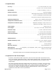
1.2. Specifications Accuracy .................................................................................... < ±0.75% full scale (F.S.) at 3σ (±1.0% F.S. for >10 slm versions) Repeatability .............................................................................±0.05% of reading + 0.02% F.S. Maximum Pressure........................................................................................500 psi [3.45 MPa] (With high pressure option) 1000 psi [6.9 MPa] Pressure Coefficient ..................
The 4-20 mA I/O option can accept a current input. The 0-5 VDC command signal on pin 14 can be replaced by a 4-20mA command signal. The loop presets an impedance of 75 ohms and is returned to the power supply through the valve common. 1.4. Other Accessories 1.4.1. Hastings Power Supplies Hastings power supplies are available in one or four channel versions. They convert 115 or 230 VAC to the ±15 VDC required to operate the flow meter.
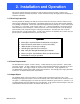
2. Installation and Operation This section contains the steps necessary to assist in getting a new flow meter/controller into operation as quickly and easily as possible. Please read the following thoroughly before attempting to install the instrument. 2.1. Receiving Inspection Carefully unpack the Hastings unit and any accessories that have also been ordered. Inspect for any obvious signs of damage to the shipment. Immediately advise the carrier who delivered the shipment if any damage is suspected.
2.4. Mechanical Connections 2.4.1. Filtering The smallest of the internal passageways in the Hastings 300 is the diameter of the sensor tube, which is 0.026”(0.66 mm), and the annular clearance for the 500 sccm shunt which is 0.006"(0.15 mm) (all other flow ranges have larger passages), so the instrument requires adequate filtering of the gas supply to prevent blockage or clogging of the tube. 2.4.2.
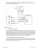
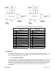
Fig. 2.1 Fig. 2.2 Figures 2.1/2.2, and Tables 2.1/2.2, show the 300/302 pin out. Table 2.1 "U" Pin-Out Pin # 1 2 3 4 5 6 7 8 9 10 11 12 13 14 15 Signal Common Do not use Do not use +15 VDC Output 0-5 VDC (4-20mA) Signal Common Case Ground Valve Override -15VDC External Input Signal Common Signal Common Set Point 0-5 VDC (4-20mA) Table 2.
2.6.2. Zero Check Turn the power supply on if not already energized. Allow for a 1 hour warm-up. Stop all flow through the instrument and wait 2 minutes. Caution: Do not assume that all metering valves completely shut off the flow. Even a slight leakage will cause an indication on the meter and an apparent zero shift. For the standard 0-5 VDC output, adjust the zero potentiometer located on the inlet side of the flow meter until the meter indicates zero (Fig 2.3).
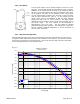
Span Error Vs. Pressure Fig. 2.5 0.017" Sensor 5% 4% Span Error (% reading) 3% 2% 1% 0% Mean Max Min -1% -2% 0 100 200 300 400 500 600 700 800 900 1000 Pressure (psig) If the system pressure is higher than 250 psig (1.7 MPa) the pressure induced error in the span reading becomes significant. The charts above show the mean error enveloped by the minimum/maximum expected span errors induced by high pressures. This error will approach 16% at 1000 psig.
External Input pin (See Tables 2.1 & 2.2), the ratio of flows can be maintained over the entire range of gas flows. EXAMPLE: Flow controller A has 0-100 slpm range with a 5.00 volt output at full scale. Flow controller B has 0-10 slpm range with a 5.00 volt output at full scale. If flow controller A is set at 80 slpm, its output voltage would be 4.00 volts (80 slpm/100 slpm x 5.00 volts = 4.00 volts).
On the controller card there is a jumper that sets whether the control loop controls mass flow or an external process variable. See Figure 2.7. If the jumper is over the top two pins, the loop controls mass flow. If the jumper is over the bottom two pins, the loop controls an external process variable. This process variable signal must be supplied on pin 12 of the D connector (for U pin out units) of the measurement card.
2.12. Temperature Coefficients As the ambient temperature of the instrument changes from the original calibration temperature, errors will be introduced into the output of the instrument. The Temperature Coefficient of Zero describes the change in the output that is seen at zero flow. This error is added to the overall output signal regardless of flow, but can be eliminated by merely adjusting the zero potentiometer of the flow meter/controller to read zero volts at zero flow conditions.
3. Theory of Operation This section contains an overall functional description of the Hastings 300 series of flow instruments. In this section and other sections throughout this manual, it is assumed that the customer is using a Hastings power supply. 3.1. Overall Functional Description The Hastings 300 meter consists of a sensor, base, and a shunt. In addition to the components in a meter, The 300 controller includes a control valve and extra electronic circuitry.
can be dissipated by radiation, conduction, or convection. The radiation term is negligible due to the low temperatures used by the sensor, and because the sensor construction preferentially favors the conductive and convective heat transfer modes. The thermal energy of each heater will then be dissipated by conduction down the stainless steel sensor tube, conduction to the insulating foam, plus the convection due to the mass flow of the sensed gas.
heater to the gas stream will force the upstream bridge control loop to apply more power to the upstream heater so that the 48oC constant differential temperature is maintained. The gas stream will increase in temperature due to the heat it gains from the upstream heater. This elevated gas stream temperature causes the heat transfer at the downstream heater to gain heat from the gas stream.
desired to ensure a stable instrument, there must be some matching between the linear volumetric flow versus pressure drop of the sensor and the shape of the volumetric flow versus pressure drop of the shunt. Most instruments employ Poiseuille’s law and use some sort of multi-passage device that creates laminar flow between the upstream sensor inlet and the downstream outlet.
(3.5) Le = Qρ 5πμ For a typical flow divider tube the entry length is approximately 0.16 cm. From this it can be seen that if the sensor inlet pickup point is inside of the flow divider tube but downstream of the entrance length and if the sensor outlet point is inside the flow divider tube but upstream of the exit point then the pressure drop that drives the flow through the sensor would be linear with respect to volumetric flow rate.
Fig. 3.5 Thickness of the annular ring as a function of flow rate for a sensor with a 75 Pa drop and a 2 cm spacing. 0.18 0.16 0.14 Passage Thickness (cm) 0.12 0.1 0.08 0.06 0.04 0.02 0 0 5 10 15 20 25 30 35 Flow (liter/min) Each shunt must have a section of the annular region upstream of the upstream sensor tap to allow the flow to become fully developed before reaching the first tap. The entry length for the annular passage is then: Le = (3.
3.7. Control Valve Fig. 3.7 The control valve is an “automatic metering solenoid” valve (see Figure 3.7). While most solenoid valves operate in either the fully open or closed positions, the automatic metering solenoid valve is designed to control flow. A spring is used to hold a magnetic plunger assembly tightly against an orifice, thereby shutting off the flow. The magnetic plunger assembly is surrounded by a coil of magnet wire.
4. Maintenance This section contains service and calibration information. Some portions of the instrument are delicate. Use extreme care when servicing the instrument. Authorized Maintenance With proper care in installation and use, the instrument will require little or no maintenance. If maintenance does become necessary, most of the instrument can be cleaned or repaired in the field. Most procedures may require recalibration. Do not attempt these procedures unless calibration references are available.
Action: Shut off all flow. For the standard 0-5VDC output, adjust the zero potentiometer located on the upper right inlet side of the flow meter until the meter indicates zero. For the optional 4-20 mA output, adjust the zero potentiometer so that the meter indicates slightly more than 4 mA, i.e. 4.03 to 4.05 mA. This slight positive adjustment ensures that the 4-20 mA transmitter is not in its cut-off region. The error induced by this adjustment is approximately 0.3% of full scale.
reverse order of disassembly. A new nickel gasket will be required. Secure the endcap with 65 in lb. (7.3 N m) to 85 in lb (9.6 N m) of torque on each stainless steel socket head cap screw. Use of a fastener other than the one mentioned here may result in leakage at the seal. Recalibration of the Hastings 300 is necessary. 4.4. Printed Circuit Board Replacement NOTE: This instrument contains static sensitive PC boards. Maintain static protection when handling the PC boards.
5. Gas Conversion Factors Gas conversion factors (GCF’s) for gasses metered using Hastings Instruments products, can be found by visiting the Hastings Instruments web site. The web address can be found at the end of this document. The gas conversion factors (GCF's) provided by Hastings Instruments (HI) fall into five basic accuracy domains that, to a large extent, are dependent on the method by which they are found. The following table summarizes the different methods used to determine the GCF's.
being used to measure the flow of propane. The reading from the meter is multiplied by the GCF for propane divided by the GCF of air. 20 * (0.3499/1.0015) = 6.9875 To calculate a target setting (20 sccm) to achieve a desired flow rate of propane using a meter calibrated to air, invert the ratio above and multiply. 20 * (1.0015/0.3499) = 57.2449 Gas conversion factors can be found at the Hastings Instruments web site. http://www.teledyne-hi.
6. Volumetric Vs Mass Flow Mass flow measures just what it says, the mass or number of molecules of the gas flowing through the instrument. Mass flow (or weight per unit time) units are given in pounds per hour (lb/hour), kilograms per sec (kg/sec) etc. When your specifications state units of flow to be in mass units, there is no reason to reference a temperature or pressure. Mass does not change based on temperature or pressure.
7. Drawings and References HFM-300 / HFC-302 Outline Drawing (All dim.
Sensor and Main PC Board TRANSDUCER HFM-300 Sectional View SHUNT ENDCAP ENDCAP 300-302 Series Page 29 of 31
TRANSDUCER VALVE ASSEMBLY CONTROLLER CARD SHUNT ENDCAP 300-302 Series ENDCAP HFC-302 Sectional View Page 30 of 31
8. WARRANTY 8.1. Warranty Repair Policy Hastings Instruments warrants this product for a period of one year from the date of shipment to be free from defects in material and workmanship. This warranty does not apply to defects or failures resulting from unauthorized modification, misuse or mishandling of the product. This warranty does not apply to batteries or other expendable parts, or to damage caused by leaking batteries or any similar occurrence.