Contents Important Safety Instructions 2 Precations 3 Features 4 Before Using This Product 5 Integrated Amplifier A-5VL Instruction Manual Thank you for purchasing an Onkyo A-5VL Integrated Amplifier. Please read this manual thoroughly before making connections and plugging in the unit. Following the instructions in this manual will enable you to obtain optimum performance and listening enjoyment from your new A-5VL. Please retain this manual for future reference.
WARNING: TO REDUCE THE RISK OF FIRE OR ELECTRIC SHOCK, DO NOT EXPOSE THIS APPARATUS TO RAIN OR MOISTURE. CAUTION: TO REDUCE THE RISK OF ELECTRIC SHOCK, DO NOT REMOVE COVER (OR BACK). NO USER-SERVICEABLE PARTS INSIDE. REFER SERVICING TO QUALIFIED SERVICE PERSONNEL.
Precautions 1. Recording Copyright—Unless it’s for personal use only, recording copyrighted material is illegal without the permission of the copyright holder. 2. AC Fuse—The AC fuse inside the unit is not user serviceable. If you cannot turn on the unit, contact your Onkyo dealer. 3. Care—Occasionally you should dust the unit all over with a soft cloth. For stubborn stains, use a soft cloth dampened with a weak solution of mild detergent and water. Dry the unit immediately afterwards with a clean cloth.
Features - Exclusive Onkyo VLSC Technology - Independent Transformers for L/R Channels - New Custom-Designed, Audio Tuned Reference Capacitors - Low-Impedance, Copper Bus Plates for Perfect Ground Potential - 40 W/Ch into 8 (FTC)-North American model, 60 W/Ch into 4 (IEC)-European, other models - 2 High-Grade 192 kHz/24-Bit D/A Converters - Optimum Gain Volume Circuitry - Precision Motor-Driven Volume Control - Tone Control (Bass/Treble On/Off) - Direct Mode - Discrete Phono Equalizer Circuitry - 4 Audio
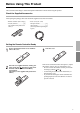
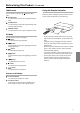
Before Using This Product This section describes things to check and important information to know before using this product. Check the Supplied Accessories After opening the package, make sure that all the supplied accessories are included. - Remote controller (RC-751S)[1] - AA (R6) batteries ..................[2] (Not supplied with products for China.) - Power cord (2 m / 6.5ft) European models .................. [2] Other models ........................ [1] (The shape differs depending on region.
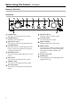
Before Using This Product—Continued Names of Each Part Front Panel POWER button This button is used to turn the unit on and off. MUTING indicator Illuminates when the volume is muted. POWER indicator Illuminates when the amp is on. VOLUME control This control adjusts the volume. Input selector control This control is used to select the playback device. DIRECT indicator Illuminates when there is direct output.
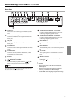
Before Using This Product—Continued Rear Panel GND screw This screw is for connecting a turntable's ground wire. AUDIO INPUT DIGITAL 1 COAXIAL Connect a digital audio input here. This is for connecting a digital playback device. PHONO (MM/MC) jacks Connect a turntable's audio output terminals into these jacks. AUDIO INPUT DIGITAL 2 OPTICAL Connect a digital audio input here. This is for connecting a digital playback device. CD jacks Connect a CD player's audio output terminals into these jacks.
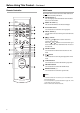
Before Using This Product—Continued Remote Controller DOCK mode This mode can be used to control an iPod mounted on an connected Onkyo RI dock. MODE button (*) You can display track information from mounted devices on the monitor. MODE DISPLAY button (*) This button illuminates the iPod's backlight. DISPLAY SELECT PLAYLIST MENU ALBUM SHUFFLE BAND PLAYLIST button Use this button to switch the current playlist. MENU button (*) Use this button to return to the previous iPod menu screen.
Before Using This Product—Continued TUNER mode Use this mode to control an connected Onkyo tuner. BAND button Use this button to switch the reception band (FM/ AM). Using the Remote Controller Point the remote controller toward the remote control sensor, within the field shown in the drawing. MODE button Use this button to switch the reception mode when receiving FM broadcasts. PRESET button Use this button to select a preset broadcast station. Approx.
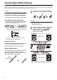
Connecting to Other Devices Connect to playback components, recording devices, and other equipment. There are two ways of connecting: analog and digital. Select the connection type matching the type of audio you wish to enjoy. Loosen the screws on the speaker terminals, insert the wires, and screw the terminals tight. ! Caution Do not place the unit in a location subject to vibration.
Connecting to Other Devices—Continued Notes Two sets of speakers can be connected to the amplifier. You can select which speakers to output audio to when listening to music. You can also output audio from both sets of speakers. - North American model: If you only connect one set of speakers (A or B), make sure to use speakers with an impedance of 2 to 16 Ohms. If you connect both sets of speakers (A and B), make sure to use speakers with an impedance of 4 to 16 Ohms.
Connecting to Other Devices—Continued Connecting a Super Audio or Normal CD Player Connect the CD player's audio outputs to the unit's CD jacks. A-5VL Connecting an AM/FM Tuner Connect the AM/FM tuner's audio outputs to the unit's TUNER inputs. Any Onkyo AM/FM tuner with the proper terminals can be connected. A connected tuner can be controlled via the unit's remote controller. Use a cable to connect the unit's terminal with the tuner's terminal.
Connecting to Other Devices—Continued Connecting a Cassette or MiniDisc Recorder Set the RI dock's MODE selector to "HDD" or "HDD/DOCK". Set the unit's input selector to "DOCK". Connect the audio outputs of the cassette or MiniDisc Recorder (PLAY) to the unit's TAPE IN jacks. Connect the audio inputs of the cassette or MiniDisc Recorder (REC) to the unit's TAPE OUT jacks. Notes Refer to the RI dock's manual for details.
Connecting to Other Devices—Continued Connecting a Digital Playback Component (COAXIAL) Connect the component using a commercial coaxial digital cable. Notes - The unit supports 16/24 bit, 32/44.1/48/96 kHz PCM signal digital input. Inputting an incompatible signal may result in noise. When an unsupported signal is detected, the unit's LOCKED indicator illuminates. Do not input a DTS-CD digital audio signal.
Enjoying Audio Sources (Operating the Unit) Turn on the component connected to the unit. Turn the VOLUME control to adjust the volume. Press the POWER button on the front of the unit to turn it on. You can also control the volume using the volume buttons on the remote controller. The POWER indicator illuminates. Notes - Audio output will not begin until the electrical circuit stabilizes. Audio quality will stabilize about 10 to 30 minutes after the unit is turned on.
Enjoying Audio Sources (Operating the Unit)—Continued Adjusting the Tone and Left/Right Volume Balance Press the DIRECT button on the front of the unit to turn it off. Recording This section describes how to record audio when both a playback component and recording component are connected to the unit. Notes Manual tone adjustments using the BASS, TREBLE, and BALANCE controls are not reflected. DIRECT off: Audio adjusted via the unit's BASS, TREBLE, and BALANCE controls is output.
Troubleshooting If you run into problems with the unit, look for a solution below. The problem could also be caused by one of the components connected to the unit, so please also check the manuals of each device. ! Caution - - This unit contains a sophisticated microcomputer for signal processing and control functions. In very rare situations, however, severe interference, noise from an external source, or static electricity may cause it to lock up.
Appendix Specifications Rated output Power Maximum Output Power Dynamic Power THD (Total Harmonic Distortion) Damping Factor Input Sensitivity and Impedance Output Level and Impeadance Phono Overload Frequency Response Tone Control Signal to Noise Ratio Speaker Impedance Digital Inputs Analog Inputs Analog Outputs Speaker Outputs Phones Power Supply Power Consumption Dimensions (WxHxD) Weight : North America 40 watts minimum continuous power per channel, 8 ohm loads, 2 channels driven at 1 kHz, with a
Appendix—Continued Block Diagram PHONO SELECTOR IC and MAIN VOLUME MM/MC CD MUTE Lch TUNER POWER AMP BALANCE BASS TREBLE TAPE OUT SPEAKER SPEAKER SPEAKERS A SPEAKERS B A B RELAY RELAY PURE DIRECT TAPE IN MUTE Rch DOCK IN DIR DAC COAX IN VLSC OPT IN DAC VLSC POWER AMP BALANCE BASS TREBLE HEADPHONE AMP SPEAKERS A SPEAKERS B HEADPHONE HEADPHONE AMP RI RI CONTROL HEADPHONE 19
Sales & Product Planning Div. : 2-1, Nisshin-cho, Neyagawa-shi, OSAKA 572-8540, JAPAN Tel: 072-831-8023 Fax: 072-831-8163 ONKYO U.S.A. CORPORATION 18 Park Way, Upper Saddle River, N.J. 07458, U.S.A. Tel: 201-785-2600 Fax: 201-785-2650 http://www.us.onkyo.com/ ONKYO EUROPE ELECTRONICS GmbH Liegnitzerstrasse 6, 82194 Groebenzell, GERMANY Tel: +49-8142-4401-0 Fax: +49-8142-4401-555 http://www.eu.onkyo.