Contents Before using CD Receiver CR-305TX Instruction Manual Important Safeguards ....................... 2 Precautions ....................................... 3 Features ............................................ 4 Supplied accessories ........................ 5 Before operating this unit ................ 5 Preparation Audio equipment connections ......... 6 Connecting speaker systems ............ 8 Connecting the AC power cord (mains lead) ......................................
WARNING: TO REDUCE THE RISK OF FIRE OR ELECTRIC SHOCK, DO NOT EXPOSE THIS APPLIANCE TO RAIN OR MOISTURE. CAUTION: TO REDUCE THE RISK OF ELECTRIC SHOCK, DO NOT REMOVE COVER (OR BACK). NO USER-SERVICEABLE PARTS INSIDE. REFER SERVICING TO QUALIFIED SERVICE PERSONNEL.
21. Replacement Parts – When replacement parts are required, be sure the service technician has used replacement parts specified by the manufacturer or have the same characteristics as the original part. Unauthorized substitutions may result in fire, electric shock, or other hazards. 22. Safety Check – Upon completion of any service or repairs to the appliance, ask the service technician to perform safety checks to determine that the appliance is in proper operation condition. 23.
For U.S. model IMPORTANT The laser is covered by a housing which prevents exposure during operation or maintenance. However, this product is classified as a Laser Product by CDRH (Center for Devices and Radiological Health) which is a department of the Food and Drug Administration. According to their regulations 21 CFR section 1002.30, all manufactures who sell Laser Products must maintain records of written communications between the manufacturer, dealers and customers concerning radiation safety.
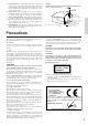
Supplied accessories Check that the following accessories are supplied with this unit. AM loop antenna × 1 RE RC -4 21 MO TE The following accessory is available on the models other than U.S. and Canadian models. FM indoor antenna × 1 75/300 ohms antenna adapter × 1 CO NT RO LL ER Remote controller (RC-421S) × 1 Batteries (size AA or UM-3) × 2 S Before operating this unit Installing the remote controller batteries 1 1. Remove the battery compartment cover by pressing and sliding it out. 2.
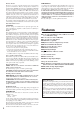
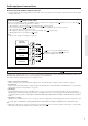
Audio equipment connections • Do not connect the AC power cord (mains lead) to the wall outlet (the mains) until you have completed all the other connections connections on page 7, and the speaker connections on page 8. including the • On each pair of connectors, a red connector (marked R) corresponds to the right channel, and a white connector (marked L) to the left channel. Connect white plugs of audio connection cables to L connectors and connect red plugs of audio connection cables to R connectors .
Audio equipment connections About the OPTICAL DIGITAL OUTPUT connector • An optical digital audio input equipped MD recorder, DAT, or CD recorder may be connected with an optical fiber audio cable for digital recording of this unit. Connecting the remote control cables If your other components are made by ONKYO and those components are equipped with connectors, you can control the connected components with the supplied remote controller. system hookups for control operations.
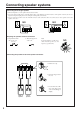
Connecting speaker systems Connecting left and right speakers • The load impedance of each speaker must be at least 4 ohms. • Do not use unnecessarily long or extremely thin speaker cords. Otherwise, the DC resistance of the speaker cords may become too high, lowering the damping factor and causing the sound quality to deteriorate. • Do not connect the speaker cord to the L and R connectors at the same time and do not connect two or more speakers to the same speaker connectors.
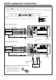
Connecting speaker systems Connecting a sub-woofer (U.S. and Canadian models) REMOTE CONTROL SPEAKERS R L FM 75 ANTENNA R AM L TAPE OUT (REC) OPTICAL (PLAY) IN DIGITAL OUTPUT Active sub-woofer OUT (REC) (PLAY) IN SUBWOOFER PRE OUT CDR R L • The SUBWOOFER PRE OUT jack supplies the left and right mixed monaural signals to the sub-woofer. Connecting the AC power cord (mains lead) Connecting the AC power cord (mains lead) 2. STANDBY/ON 1.
Making antenna connections Assembling the AM loop antenna Assemble the loop antenna as shown in the illustration. Insert into the hole. 1 2 3 Connecting the antenna cable 1. Press down the lever. 2. Insert the wire into the hole. 3. Release the lever to replace it. Asian and European models U.S. and Canadian models Connecting the included antennas Connecting the FM indoor antenna The FM indoor antenna is for indoor use only.
Making antenna connections Connecting an FM outdoor antenna Please make sure that you follow the considerations below regarding the location. Keep the antenna away from noise sources (neon signs, busy roads, etc.). It is dangerous to put the antenna close to power lines. Keep it well away from power lines, transformers, etc. FM 75 ANTENNA AM • To avoid the risk of lightning and electrical shock, grounding is necessary.
Control positions and names 1 2 3 4 5 6 7 8 9 TUNING/PRESET VOLUME STANDBY/ON MEMORY FM MODE INPUT U S TIC P R E S E N CE DISPLAY AC O CLEAR PHONES MIN 15 14 a Display b c TIMER CD W.DAY W.END MEMORY REC REPEAT SLEEP RANDOM s r 13 12 d e f g TRACK AUTO MONO AM PM q For more information about buttons or knobs, refer to the pages listed in the brackets ( [ ] ) below. 7. 8. 9. 10. 11. 12. 13. 14. 15.
Remote controller RC-421S For more information about buttons or knobs, refer to the pages listed in the brackets ( [ ] ) below. REMOTE CONTROLLER STANDBY/ON INPUT 1 2 TIMER 10 ENTER RANDOM 3 CD MEMORY REPEAT SCROLL 4 MD PLAY MODE REPEAT SLEEP UME UP VOL A.PRESENCE 11 5 6 CLOCK CALL 7 8 VOLUME MUTING VO LUME DO PLAY MODE REPEAT WN CDR TAPE 9 12 1. STANDBY/ON button [9] Toggles between STANDBY and ON. 2.
Setting the clock REMOTE CONTROLLER STANDBY/ON TIMER INPUT TIMER ENTER RANDOM MEMORY REPEAT ENTER CD SCROLL PLAY MODE REPEAT SLEEP CLOCK CALL VOL MD UME UP A.PRESENCE VOLUME MUTING VO LU M E D O W N PLAY MODE REPEAT CDR TAPE TUNER PRESET RC-421S 1 Setting the clock TIMER 1. Press the TIMER button until “ADJUST” is selected on the display, then press the ENTER button. The day of the week will flash on the display. ENTER buttons to set the desired time. 3. Use the 4.
Setting the clock REMOTE CONTROLLER STANDBY/ON TIMER INPUT TIMER ENTER RANDOM MEMORY REPEAT ENTER CD SCROLL PLAY MODE REPEAT SLEEP CLOCK CALL CLOCK CALL VOL MD UME UP A.PRESENCE VOLUME MUTING VO LU M E D O W N PLAY MODE REPEAT CDR TAPE TUNER PRESET RC-421S Switching between the 24 hour and 12 hour display settings 1 TIMER 1. Press the TIMER button repeatedly to display “24H/12H.” 2. Press the ENTER button. “24H” or “12H” flashes on the display.
Choosing the required source REMOTE CONTROLLER VOLUME STANDBY/ON INPUT TIMER INPUT ENTER RANDOM MEMORY REPEAT CD SCROLL PLAY MODE REPEAT MD TUNING/PRESET SLEEP VOLUME DISPLAY INPUT E USTIC PRESENC STANDBY/ON MEMORY FM MODE ACO CLEAR PHONES MIN VOLUME / MAX CLOCK CALL VOL UME UP 1 ACOUSTIC Indicator PRESENCE Remote controller A. PRESENCE VOLUME MUTING VO LU M E D O W N PLAY MODE REPEAT INPUT A.
Muting / Listening with the headphones REMOTE CONTROLLER STANDBY/ON INPUT TIMER ENTER RANDOM MEMORY REPEAT CD SCROLL PLAY MODE REPEAT MD TUNING/PRESET SLEEP VOLUME DISPLAY INPUT E USTIC PRESENC STANDBY/ON MEMORY FM MODE VOLUME / ACO CLEAR PHONES MIN MAX CLOCK CALL VOL UME UP A.PRESENCE VOLUME MUTING VO LU M E D O W N PLAY MODE REPEAT MUTING CDR TAPE PHONES TUNER PRESET RC-421S Muting the sound Press the MUTING button on the remote controller to mute the sound.
Playing a CD , REMOTE CONTROLLER STANDBY/ON INPUT TIMER INPUT ENTER RANDOM MEMORY REPEAT CD , SCROLL PLAY MODE REPEAT MD TUNING/PRESET SLEEP VOLUME DISPLAY INPUT E USTIC PRESENC STANDBY/ON MEMORY FM MODE ACO CLEAR PHONES CLOCK CALL VOL A.PRESENCE VOLUME MUTING VO MIN UME UP MAX LU M E D O W N PLAY MODE REPEAT CDR TAPE INPUT TUNER PRESET RC-421S Playing a CD 1 Label side 1. Press the button to open the disc tray, and put the CD in the tray with the label side facing up.
Playing a CD REMOTE CONTROLLER STANDBY/ON INPUT TIMER RANDOM ENTER RANDOM MEMORY REPEAT REPEAT CD SCROLL PLAY MODE REPEAT SLEEP CLOCK CALL VOL MD UME UP A.PRESENCE VOLUME MUTING VO LU M E D O W N PLAY MODE REPEAT CDR TAPE TUNER PRESET RC-421S RANDOM playback (remote controller only) All the tracks on the disc will be shuffled, then played back. To start RANDOM playback, press the RANDOM button while the CD is stopped, or press the RANDOM button during playback.
Playing a CD , REMOTE CONTROLLER STANDBY/ON DISPLAY INPUT TIMER ENTER RANDOM MEMORY MEMORY REPEAT CD , SCROLL PLAY MODE REPEAT MD TUNING/PRESET SLEEP VOLUME DISPLAY INPUT E USTIC PRESENC STANDBY/ON MEMORY FM MODE ACO CLEAR PHONES CLOCK CALL VOL MAX A.
Playing a CD Changing the display information Pressing the DISPLAY button repeatedly during playback will change the display information as follows: The elapsed time of the playing track Programmed memory number (P-00) (Shown in MEMORY playback mode only) The remaining time of the playing track ( S lights up) Total remaining time of the disc or the total time of the programmed tracks (shown in MEMORY playback mode only) ( T lights up) Note “– –:– –” will be displayed, • if the playing track number is 21
Receiving stations TUNING/PRESET REMOTE CONTROLLER STANDBY/ON INPUT TIMER INPUT ENTER RANDOM MEMORY REPEAT CD SCROLL PLAY MODE REPEAT MD TUNING/PRESET SLEEP VOLUME DISPLAY INPUT E USTIC PRESENC STANDBY/ON MEMORY FM MODE ACO CLEAR PHONES CLOCK CALL VOL MAX MUTING LU M E D O W N PLAY MODE REPEAT MEMORY A.PRESENCE VOLUME VO MIN UME UP CDR TAPE INPUT TUNER PRESET RC-421S Tuning the radio 1 Remote controller INPUT INPUT 1.
Receiving stations REMOTE CONTROLLER TUNING/PRESET STANDBY/ON INPUT TIMER INPUT ENTER RANDOM MEMORY REPEAT CD SCROLL PLAY MODE REPEAT MD TUNING/PRESET SLEEP VOLUME STANDBY/ON MEMORY FM MODE INPUT E USTIC PRESENC DISPLAY CLOCK CALL ACO CLEAR PHONES VOL MAX MUTING LU M E D O W N PLAY MODE REPEAT MEMORY A.
Receiving stations REMOTE CONTROLLER TUNING/PRESET STANDBY/ON INPUT TIMER INPUT ENTER RANDOM MEMORY REPEAT CD SCROLL PLAY MODE REPEAT MD TUNING/PRESET SLEEP VOLUME STANDBY/ON MEMORY FM MODE INPUT E USTIC PRESENC DISPLAY CLOCK CALL ACO CLEAR PHONES VOL MAX MUTING LU M E D O W N PLAY MODE REPEAT TUNER /PRESET MEMORY FM MODE INPUT A.
Receiving stations DISPLAY TUNING/PRESET VOLUME DISPLAY INPUT E USTIC PRESENC STANDBY/ON MEMORY FM MODE ACO CLEAR PHONES MIN MAX Receiving RDS (European models only) RDS reception is available only on the European models, and only in areas where RDS broadcasts are available. Program service name Frequency DISPLAY What is RDS? Many FM stations now transmit RDS signals which contain additional information.
Using the timer The CR-305TX features a Timer function that enables you to start playing or recording a specified component at a specified time. To use this REMOTE CONTROL jacks. Refer to “Connecting the remote control function, you need to connect this unit to other components via remote control cables?” on page 7 for more cables” and “What can you do with the other ONKYO components by connecting with an information on making the connections.
Using the timer REMOTE CONTROLLER STANDBY/ON TIMER INPUT TIMER ENTER RANDOM MEMORY REPEAT ENTER CD SCROLL PLAY MODE REPEAT SLEEP CLOCK CALL VOL MD UME UP A.PRESENCE VOLUME MUTING VO LU M E D O W N PLAY MODE REPEAT CDR TAPE TUNER PRESET RC-421S Changing the WEEKDAY and WEEKEND settings Sunday Monday Tuesday Saturday Friday Thursday You can define or change which day is WEEKDAY or WEEKEND.
Using the timer REMOTE CONTROLLER STANDBY/ON TIMER STANDBY/ON INPUT TIMER ENTER ENTER RANDOM MEMORY REPEAT CD SCROLL PLAY MODE REPEAT SLEEP CLOCK CALL VOL MD UME UP A.PRESENCE VOLUME MUTING VO LU M E D O W N PLAY MODE REPEAT CDR TAPE TUNER PRESET RC-421S 1 Programming to play at a specified time TIMER The clock of this unit must be set correctly before programming the timer.
Using the timer REMOTE CONTROLLER STANDBY/ON INPUT TIMER TIMER ENTER RANDOM MEMORY REPEAT ENTER CD SCROLL PLAY MODE REPEAT SLEEP CLOCK CALL VOL MD UME UP A.PRESENCE VOLUME MUTING VO LU M E D O W N PLAY MODE REPEAT CDR TAPE TUNER PRESET RC-421S 1 Programming to record at a specified time TIMER REC mode of the Timer function enables you to record a specified source at a specified time.
Using the timer REMOTE CONTROLLER STANDBY/ON TIMER STANDBY/ON INPUT TIMER ENTER ENTER RANDOM MEMORY REPEAT CD SCROLL PLAY MODE REPEAT SLEEP CLOCK CALL VOL MD UME UP A.PRESENCE VOLUME MUTING VO LU M E D O W N PLAY MODE REPEAT CDR TAPE TUNER PRESET RC-421S 6 TIMER STEREO REC 6. If you are using U. S. or Canadian models, skip this step. If butyou are using Asian or European models, press the tons to select the recording component, and press the ENTER button.
Using the timer REMOTE CONTROLLER STANDBY/ON INPUT TIMER ENTER RANDOM MEMORY REPEAT CD SCROLL PLAY MODE REPEAT SLEEP SLEEP CLOCK CALL VOL MD UME UP A.PRESENCE VOLUME MUTING VO LU M E D O W N PLAY MODE REPEAT CDR TAPE TUNER PRESET RC-421S Sleep function The Sleep function can be performed only by using remote controller. The SLEEP timer automatically sets the entire system to Standby mode after a specified period of time. SLEEP AUTO STEREO MIN SLEEP 1.
Troubleshooting If you have any problems with the unit, please check the troubleshooting table below first. For any problems not covered in the table, please consult your nearest ONKYO authorized service center. Trouble Remedy The unit doesn't turn on. • The AC power cord is not fully inserted into the wall outlet. • Insert the AC power cord (mains lead) plug into the wall outlet (the mains) securely. 9 Sound is reproduced from neither left or right speaker.
Troubleshooting Trouble Cause Remedy See page The disc skips sounds. • Vibrations are being transmitted to the unit. • The disc is severely scratched. • The disc is extremely dirty. • Place the unit in a vibration free location. • Replace the disc with a new one. • Clean the disc. – 21 21 Track numbers cannot be stored when setting MEMORY playback. • There is no disc inserted in the unit. • A track number not on the disc is being input. • Insert a disc into the unit.
Specifications AMPLIFIER TUNER 2 × 20 watts at 4 ohms 1 kHz DIN 2 × 17 watts at 6 ohms 1 kHz DIN 2 × 15 watts at 8 ohms 1 kHz DIN 2 × 20 watts min, RMS at 4 ohms 1 kHz no more than 1 % THD (FTC rating) 2 × 25 watts at 4 ohms EIAJ Dynamic Power: 2 × 24 watts at 4 ohms 2 × 18 watts at 8 ohms Total Harmonic Distortion: 0.2 % at 10 watts output IM Distortion: 0.
Using the remote controller Listening to the radio STANDBY/ON INPUT TIMER ENTER 1 RANDOM MEMORY REPEAT CD 1. Select FM or AM using the INPUT buttons. buttons to select the desired 2. Use the TUNER PRESET preset station. SCROLL PLAY MODE REPEAT SLEEP CLOCK CALL VOL A.PRESENCE VOLUME MUTING VO LUME DO WN PLAY MODE REPEAT 2 MD UME UP CDR TAPE TUNER PRESET STANDBY/ON INPUT TIMER ENTER 1 RANDOM MEMORY REPEAT CD SLEEP CLOCK CALL MD UME UP VOL A.
Sales & Product Planning Div. : 2-1, Nisshin-cho, Neyagawa-shi, OSAKA 572-8540, JAPAN Tel: 072-831-8111 Fax: 072-833-5222 http://www.onkyo-intl.com ONKYO U.S.A. CORPORATION 18 Park Way, Upper Saddle River, N.J. 07458, U.S.A. Tel: 201-785-2600 Fax: 201-785-2650 http://www.onkyousa.com ONKYO EUROPE ELECTRONICS GmbH Liegnitzerstrasse 6, 82194 Groebenzell, GERMANY Tel: +49-8142-4401-0 Fax: +49-8142-4401-555 http://www.onkyo.