Contents AV RECEIVER HT-RC430 Safety Information and Introduction ............2 Table of Contents ...........................................5 Connections .................................................11 Turning On & Basic Operations..................19 Instruction Manual Advanced Operations ..................................35 Controlling Other Components...................46 Appendix .......................................................
Safety Information and Introduction WARNING: TO REDUCE THE RISK OF FIRE OR ELECTRIC SHOCK, DO NOT EXPOSE THIS APPARATUS TO RAIN OR MOISTURE. CAUTION: TO REDUCE THE RISK OF ELECTRIC SHOCK, DO NOT REMOVE COVER (OR BACK). NO USER-SERVICEABLE PARTS INSIDE. REFER SERVICING TO QUALIFIED SERVICE PERSONNEL.
Safety Information and Introduction Precautions 1. Recording Copyright—Unless it’s for personal use only, recording copyrighted material is illegal without the permission of the copyright holder. 2. AC Fuse—The AC fuse inside the unit is not userserviceable. If you cannot turn on the unit, contact your Onkyo dealer. 3. Care—Occasionally you should dust the unit all over with a soft cloth. For stubborn stains, use a soft cloth dampened with a weak solution of mild detergent and water.
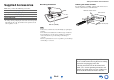
Safety Information and Introduction Supplied Accessories ■ Installing the batteries Make sure you have the following accessories: Indoor FM antenna (➔ page 18) ■ Aiming the remote controller To use the remote controller, point it at the AV receiver’s remote control sensor, as shown below.
Safety Information and Introduction Table of Contents Safety Information and Introduction Important Safety Instructions ......................................2 Precautions ...................................................................3 Supplied Accessories...................................................4 Table of Contents..........................................................5 Features .........................................................................6 Front & Rear Panels.................
Safety Information and Introduction Features Connections • 60 Watts/Channel @ 8 ohms (FTC) • Optimum Gain Volume Circuitry • H.C.P.S. (High Current Power Supply) Massive High Power Transformer • 4 HDMI Inputs and 1 Output • Onkyo p for System Control • 3 Digital Inputs (2 Optical/1 Coaxial) • Component Video Switching (2 Inputs/1 Output) • Front-Panel USB Input for Memory Devices and iPod®/iPhone® models Processing Miscellaneous • HDMI (Audio Return Channel, 3D, DeepColor, x.v.
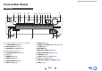
Safety Information and Introduction Front & Rear Panels Front Panel a op cd b e q f g h ij k l m r For detailed information, see the pages in parentheses.
Safety Information and Introduction Display a b c d e g f h For detailed information, see the pages in parentheses. a A and B speaker indicators (31) b M.
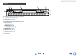
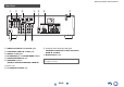
Safety Information and Introduction Rear Panel a b c h d i e f g j a DIGITAL IN COAXIAL and OPTICAL jacks b COMPONENT VIDEO IN and OUT jacks c HDMI IN and OUT jacks d FM ANTENNA jack and AM ANTENNA terminal e SUBWOOFER PRE OUT jack f SPEAKERS terminals (FRONT A, CENTER, SURROUND, FRONT B) i Composite video and analog audio jacks (BD/DVD IN, VCR/DVR IN and OUT, CBL/SAT IN, GAME IN, TV/CD IN) j MONITOR OUT V jack See “Connecting the AV Receiver” for connection (➔ pages 11 to 18).
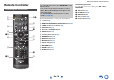
Safety Information and Introduction Remote Controller Controlling the AV Receiver a b c d ae f ic To control the AV receiver, press RECEIVER to select Receiver mode. You can also use the remote controller to control Onkyo Blu-ray Disc/DVD player, CD player, and other components. See “Entering Remote Control Codes” for more details (➔ page 48). For detailed information, see the pages in parentheses.
Connections Connecting the AV Receiver Surround right Surround left Connecting Your Speakers Connecting the Speaker Cables The following illustration shows how to connect the speakers to each pair of terminals. ■ Push-type speaker terminals Strip 3/8" to 1/2" (10 to 12 mm) of insulation from the ends of the speaker cables, and twist the bare wires tightly, as shown.
Connections Speaker Configuration Attaching the Speaker Cable Labels The following table indicates the channels you should use depending on the number of speakers that you have. No matter how many speakers you use, a powered subwoofer is recommended for a really powerful and solid bass. To get the best from your surround sound system, you need to set the speaker settings manually (➔ page 38). The speaker terminals are color-coded for identification purpose.
Connections Speaker Connection Precautions Read the following before connecting your speakers: • You can connect speakers with an impedance of between 6 and 16 ohms. If you use speakers with a lower impedance, and use the amplifier at high volume levels for a long period of time, the built-in amp protection circuit may be activated. • Disconnect the power cord from the wall outlet before making any connections. • Read the instructions supplied with your speakers.
Connections AV Cables and Jacks About AV Connections ■ HDMI HDMI connections can carry digital video and audio. Connecting AV components a HDMI cable ■ Optical digital audio Optical digital connections allow you to enjoy digital sound such as PCM*1, Dolby Digital or DTS. The audio quality is the same as coaxial. : Video & Audio TV, projector, etc.
Connections Connecting Components with HDMI VCR or DVD recorder/digital video recorder Game console TV, projector, etc. Satellite/cable set-top box, etc. * * Blu-ray Disc/DVD player If your TV doesn’t support Audio Return Channel (ARC), you need to connect an optical digital cable together with the HDMI cable to the AV receiver.
Connections Connecting Your Components A BC The on-screen menus appear only on a TV that is connected to the HDMI OUT. If your TV is connected to other video outputs, use the AV receiver’s display when changing settings. Note *1 *2 ✔: Assignment can be changed (➔ pages 37, 38). No. Jack/Port A Components *3 AUX INPUT VIDEO Camcorder, etc.
Connections Connecting a Recording Component Connecting Onkyo u Components 1 Make sure that each Onkyo component is connected with an analog audio cable (connection F in the hookup examples) (➔ page 16). 2 3 Make the u connection (see the illustration). See “Recording” for details on recording (➔ page 34). If you’re using an RI Dock or cassette tape deck, change the Input Display (➔ page 33). With u (Remote Interactive), you can use the following special functions: e.g.
Connections Connecting the Antennas Connecting the Power Cord This section explains how to connect the supplied indoor FM antenna and AM loop antenna. The AV receiver won’t pick up any radio signals without any antenna connected, so you must connect the antenna to use the tuner. 1 Plug the power cord into an AC wall outlet. Note • Before connecting the power cord, connect all of your speakers and AV components.
Turning On & Basic Operations Turning On/Off the AV Receiver 8ON/STANDBY Turning On 1 Turning Off Press 8ON/STANDBY on the front panel. or Press RECEIVER followed by 8 on the remote controller. The AV receiver comes on, and its display lights. 1 Press 8ON/STANDBY on the front panel. or Press RECEIVER followed by 8 on the remote controller. The AV receiver will enter standby mode. To prevent any loud surprises when you turn on the AV receiver, always turn down the volume before you turn it off.
Turning On & Basic Operations Playback The on-screen menus appear only on a TV that is connected to the HDMI OUT. If your TV is connected to other video outputs, use the AV receiver’s display when changing settings. Playing the Connected Component ■ Operating on the AV receiver Input selector buttons ■ Operating with the remote controller LISTENING MODE MASTER VOLUME INPUT SELECTOR RECEIVER VOL q/w This section describes the procedure for using the remote controller unless otherwise specified.
Turning On & Basic Operations Controlling Contents of USB Devices h a TOP MENU This button displays the top menu for each media or service. o RANDOM This button performs random playback. b q/w and ENTER These buttons navigate through the menus. p REPEAT Press this button repeatedly to cycle through the repeat modes. e/r This button cycles through pages. PLAYLIST e/r In Standard Mode (iPod/iPhone), this button selects playlists. Press USB first. i c 1 This button starts playback.
Turning On & Basic Operations Understanding Icons on the Display This section describes icons that appear on the AV receiver’s display during media playback. Icon Playing an iPod/iPhone via USB The on-screen menus appear only on a TV that is connected to the HDMI OUT. Description Folder Track Playback Pause Fast Forward Fast Reverse This section explains how to play music files on the iPod/iPhone.
Turning On & Basic Operations Playing a USB Device The on-screen menus appear only on a TV that is connected to the HDMI OUT. This section explains how to play music files from a USB device (e.g., USB flash drives and MP3 players). See also: • “USB Features” (➔ page 61) 1 2 Press USB to select the “USB” input. Plug your USB device into the AV receiver’s USB port. While reading the contents of your USB device, the message “Connecting...” appears on the AV receiver’s display. 3 Press ENTER.
Turning On & Basic Operations Listening to AM/FM Radio This section describes the procedure using the buttons on the front panel unless otherwise specified. Using the Tuner With the built-in tuner you can enjoy AM and FM radio stations. You can store your favorite stations as presets for quick selection. You can also change the frequency steps (➔ page 42). 1 ■ Auto tuning mode 1 Press TUNING MODE so that the AUTO indicator lights on the AV receiver’s display. 2 Press TUNING q/w.
Turning On & Basic Operations Presetting AM/FM Stations ■ Selecting Presets You can store a combination of up to 40 of your favorite AM/FM radio stations as presets. 1 1 Tune into the AM/FM station that you want to store as a preset. See the previous section. 2 Press MEMORY. The preset number flashes. (Actual display depends on the country.) 3 While the preset number is flashing (about 8 seconds), use PRESET e/r to select a preset from 1 through 40.
Turning On & Basic Operations Using Basic Functions MOVIE/TV button This button selects the listening modes intended for use with movies and TV. MUSIC button This button selects the listening modes intended for use with music. GAME button This button selects the listening modes intended for use with video games. STEREO button This button selects the Stereo listening mode and All Channel Stereo listening mode.
Turning On & Basic Operations About Listening Modes The AV receiver’s listening modes can transform your listening room into a movie theater or concert hall, with high fidelity and stunning surround sound. ■ Explanatory Notes a b Input Source The following audio formats are supported by the listening mode. A This is mono (monophonic) sound. S This is stereo (stereophonic) sound. Two independent audio signal channels are reproduced through two speakers. D This is 5.1-channel surround sound.
Turning On & Basic Operations ■ Onkyo-Original DSP Listening Modes Listening Mode Description Orchestra*1 Suitable for classical or operatic music, this mode emphasizes the surround channels in order to widen the stereo image, and simulates the natural reverberation of a large hall.
Turning On & Basic Operations ■ Listening Modes Listening Mode Description Direct In this mode, audio from the input source is output without surround-sound processing. The speaker configuration (presence of speakers) and speaker distance settings are enabled, but much of the processing set via Home menu is disabled. A/V Sync does not have effect on the analog audio. See “Onscreen Setup” for more details (➔ page 35).
Turning On & Basic Operations Listening Mode Dolby Pro Logic II PL Mo v i e PL Mu s i c PL Game Neo:6 Description Input Source Speaker Layout Dolby Pro Logic II expands any 2-channel source for 5.1-channel playback. It provides a very natural and seamless surround-sound experience that fully envelops the listener. As well as music and movies, video games can also benefit from the dramatic spatial effects and vivid imaging.
Turning On & Basic Operations The Home menu provides quick access to frequently used settings. You can change settings and view the current information. ■ Listening Mode*2 ` You can select the listening modes that are grouped in the following categories: “MOVIE/TV”, “MUSIC” and “GAME”. Use q/w to select the category and e/r to select the listening mode. Press ENTER to switch to the selected listening mode. The on-screen menus appear only on a TV that is connected to the HDMI OUT.
Turning On & Basic Operations Using the Sleep Timer With the sleep timer, you can set the AV receiver to turn off automatically after a specified period. 1 Press RECEIVER once followed by SLEEP repeatedly to select the required sleep time. The sleep time can be set from 90 to 10 minutes in 10 minute steps. The SLEEP indicator lights on the AV receiver’s display when the sleep timer has been set. The specified sleep time appears for about 5 seconds, then the previous display reappears.
Turning On & Basic Operations Changing the Input Display When you connect an u-capable Onkyo component, you must configure the input display so that u can work properly. This setting can be done only from the front panel. Press and hold down the same button (about 3 seconds) to change the input display. Repeat this step to select the desired input display. ■ TV/CD: TV/CD → DOCK TAPE ■ GAME: GAME ↔ DOCK → 2 Press TV/CD, GAME or VCR/DVR.
Turning On & Basic Operations Using Headphones 1 Connect a pair of stereo headphones with a standard plug (1/4 inch or 6.3 mm) to the PHONES jack. Note • Always turn down the volume before connecting your headphones. • While the headphones plug is inserted in the PHONES jack, the speakers are turned off. • When you connect a pair of headphones, the listening mode is set to Stereo, unless it’s already set to Stereo, Mono, or Direct.
Advanced Operations On-screen Setup Common Procedures in Setup Menu The setup menus provides a convenient way to change the AV receiver’s various settings. Settings are organized into 10 categories. a Remote indicator The on-screen menus appear only on a TV that is connected to the HDMI OUT. If your TV is connected to other video outputs, use the AV receiver’s display when changing settings.
Advanced Operations Setup menu items Menu item Setting target Level Cal (➔ page 39) Left Center Menu item Setting target HDMI Input (➔ page 37) BD/DVD Right VCR/DVR Surround Right CBL/SAT Surround Left Subwoofer GAME AUX TV/CD Component (➔ page 37) Audio Adjust (➔ page 40) Panorama VCR/DVR Dimension CBL/SAT Center Width GAME Center Image TV/CD Listening Angle BD/DVD Source Setup (➔ page 41) GAME AUX Sp Distance (➔ page 39) Volume OSD Remote ID AM/FM Freq Step Auto Standby Subw
Advanced Operations HDMI Input 1 2 Menu Component (Component Video Input) Note 3 4 5 6 HDMI Input If you connect a video component to an HDMI input, you must assign that input to an input selector. For example, if you connect your Blu-ray Disc/DVD player to HDMI IN 2, you must assign “HDMI2” to the “BD/DVD” input selector. Here are the default assignments.
Advanced Operations Digital Audio (Digital Audio Input) 1 2 3 4 5 Sp Config (Speaker Configuration) 6 1 2 3 4 5 6 ■ Front `Small: `Large: Select based on the cone diameter. Note Menu Digital Audio If you connect a component to a digital audio input, you must assign that input to an input selector. For example, if you connect your CD player to the OPTICAL IN 1, you must assign “OPTICAL1” to the “TV/CD” input selector. Here are the default assignments.
Advanced Operations Note • For a more accurate setting, look up the frequency response in the manuals supplied with your speakers and set accordingly. • Choose a higher crossover frequency if you want more sound from your subwoofer. ■ Double Bass ` On ` Off Turn this setting on to boost bass output by feeding bass sounds from the front left, right, and center channels to the subwoofer.
Advanced Operations Audio Adjust 1 2 3 Menu 4 5 6 Audio Adjust With the Audio Adjust functions and settings, you can adjust the sound and listening modes as you like. Multiplex/Mono ■ Multiplex Input Ch (Mux) ` Main ` Sub ` Main/Sub This setting determines which channel of a stereo multiplex source is output. Use it to select audio channels or languages with multiplex sources, multilingual TV broadcasts, and so on.
Advanced Operations Source Setup 1 2 3 4 5 6 Items can be set individually for each input selector. Preparation Press the input selector buttons to select an input source. Menu Source Setup A/V Sync ■ A/V Sync ` 0 ms to 400 ms in 10 msec steps When using progressive scanning on your Blu-ray Disc/DVD player, you may find that the picture and sound are out of sync. With this setting, you can correct this by delaying the audio signals. To view the TV picture while setting the delay, press ENTER.
Advanced Operations Setting the Incoming Digital Signal (Fixed Mode) ■ Fixed Mode ` Off: The format is detected automatically. If no digital input signal is present, the corresponding analog input is used instead. ` PCM: Only 2-channel PCM format input signals will be heard. If the input signal is not PCM, the PCM indicator will flash and noise may also be produced. ` DTS: Only DTS (but not DTS-HD) format input signals will be heard.
Advanced Operations • When the source equipment is connected with the u connection, it may malfunction if “HDMI Ctrl (RIHD)” is set to “On”. HDMI Setup 1 Menu 2 3 4 5 6 HDMI Setup ■ HDMI Ctrl (RIHD) ` Off ` On Turn this setting on to allow p-compatible components connected via HDMI to be controlled by the AV receiver (➔ page 58). Note • When the setting is set to “On” and the menu is closed, the names of connected p-compatible components and “RIHD On” are displayed on the AV receiver.
Advanced Operations ■ Audio Return Ch (ARC) ` Off ` Auto: The audio signal from your TV tuner can be sent to the HDMI OUT of the AV receiver. The audio return channel (ARC) function allows an ARC capable TV to send the audio stream to the HDMI OUT of the AV receiver. To use this function, you must select the TV/CD input selector and your TV must be ARC capable. Default setting: “- - - -” Note • This setting is fixed to “- - - -” when the “HDMI Ctrl (RIHD)” setting is set to “Off”.
Advanced Operations Late Night Music Optimizer CinemaFILTER ■ Late Night For Dolby Digital and Dolby Digital Plus sources, the options are: ` Off ` Low: Small reduction in dynamic range. ` High: Large reduction in dynamic range. ■ Music Optimizer ` Off ` On The Music Optimizer function enhances the sound quality of compressed music files. The M.Opt indicator lights on the AV receiver’s display.
Controlling Other Components iPod/iPhone Playback via Onkyo Dock Using the Onkyo Dock The Dock is sold separately. Models sold are different depending on the region. For the latest information on the Onkyo Dock components, see the Onkyo web site at: http://www.onkyo.com Before using the Onkyo Dock components, update your iPod/iPhone with the latest software, available from the Apple web site. For supported iPod/iPhone models, see the instruction manual of the Onkyo Dock.
Controlling Other Components ■ u Dock operation Controlling Your iPod/iPhone By pressing the REMOTE MODE button that’s been programmed with the remote control code for your Dock, you can control your iPod/iPhone in the Dock with the buttons described further in this section. See “Entering Remote Control Codes” for details on entering a remote control code (➔ page 48). See the Dock’s instruction manual for more information. Press the appropriate REMOTE MODE button first.
Controlling Other Components Controlling Other Onkyo Components You can use the AV receiver’s remote controller to control your other Onkyo AV components. This section explains how to enter the remote control code for a component that you want to control: DVD, CD, etc. Preprogrammed Remote Control Codes Entering Remote Control Codes You’ll need to enter a code for each component that you want to control.
Controlling Other Components Controlling Onkyo components without u If you want to control an Onkyo component by pointing the remote controller directly at it, or you want to control an Onkyo component that’s not connected via u, use the following remote control codes: ` 30627: Onkyo DVD player without u ` 71817: Onkyo CD player without u ` 32900/33000: Onkyo Blu-ray Disc player ` 32901/33004: Onkyo HD DVD player ` 70868: Onkyo MD recorder without u ` 71323: Onkyo CD recorder without u ` 82990: Onkyo Dock w
Controlling Other Components Controlling Other Components By pressing the REMOTE MODE button that’s been programmed with the remote control code for your component, you can control Onkyo component as described below. For details on entering a remote control code for other components, see “Entering Remote Control Codes” (➔ page 48). *1 The p supported by the AV receiver is the CEC system control function of the HDMI standard.
Controlling Other Components ■ CD player / CD recorder / MD recorder operation Press the appropriate REMOTE MODE button first.
Appendix Troubleshooting If you have any trouble using the AV receiver, look for a solution in this section. If you can’t resolve the issue yourself, contact your Onkyo dealer. If you can’t resolve the issue yourself, try resetting the AV receiver before contacting your Onkyo dealer. To reset the AV receiver to its factory defaults, turn it on and, while holding down VCR/DVR, press 8ON/STANDBY. “Clear” will appear on the AV receiver’s display and the AV receiver will enter standby mode.
Appendix If the input signal format is set to “PCM” or “DTS”. 42 Set it to “Off”. ■ Only the front speakers produce sound When the Stereo or Mono listening mode is selected, 29 only the front speakers and subwoofer produce sound. Make sure the speakers are configured correctly. 38 If you use the Dolby Pro Logic II Movie, Dolby Pro — Logic II Music, or Dolby Pro Logic II Game listening mode with a mono source, such as an AM radio station or mono TV program, the sound is concentrated in the center speaker.
Appendix Video ■ There’s no picture Make sure that all video connecting plugs are pushed 14 in all the way. Make sure that each video component is properly connected. 15, 17 If the video source is connected to a component video 16, 37 input, you must assign that input to an input selector, and your TV must be connected to COMPONENT VIDEO OUT. If the video source is connected to a composite video 16 input, your TV must be connected to the corresponding composite video output.
Appendix ■ The AV receiver’s remote controller doesn’t control my iPod/iPhone Make sure your iPod/iPhone is properly inserted in — the Dock. If your iPod/iPhone is in a case, it may not connect properly to the Dock. Always remove your iPod/iPhone from the case before inserting it into the Dock. The iPod/iPhone cannot be operated while it’s displaying the Apple logo. — Make sure you’ve selected the right remote mode. 47 When you use the AV receiver’s remote controller, point it toward your AV receiver.
Appendix The AV receiver contains a microcomputer for signal processing and control functions. In very rare situations, severe interference, noise from an external source, or static electricity may cause it to lockup. In the unlikely event that this happens, unplug the power cord from the wall outlet, wait at least five seconds, and then plug it back in. Onkyo is not responsible for damages (such as CD rental fees) due to unsuccessful recordings caused by the unit’s malfunction.
Appendix Connection Tips and Video Signal Path The AV receiver supports several connection formats for compatibility with a wide range of AV equipment. The format you choose will depend on the formats supported by your components. Use the following sections as a guide. The on-screen menus appear only on a TV that is connected to the HDMI OUT. If your TV is connected to other video outputs, use the AV receiver’s display when changing settings.
Appendix Using an RIHDcompatible TV, Player, or Recorder p, which stands for Remote Interactive over HDMI, is the name of the system control function found on Onkyo components. The AV receiver can be used with CEC (Consumer Electronics Control), which allows system control over HDMI and is part of the HDMI standard. CEC provides interoperability between various components, however, operation with components other than p-compatible components cannot be guaranteed.
Appendix ■ How to connect and setup 1 2 Confirm the connecting and setting. 1. Connect the HDMI OUT jack to the HDMI input jack of the TV. See details of each setting (➔ pages 43, 44). Blu-ray Disc/DVD player, etc. 3 HDMI connection AV receiver DIGITAL AUDIO connection (OPTICAL) HDMI connection TV, projector, etc. 2. Connect the audio output from the TV to the OPTICAL IN 2 jack of the AV receiver using an optical digital cable.
Appendix About HDMI Designed to meet the increased demands of digital TV, HDMI (High Definition Multimedia Interface) is a new digital interface standard for connecting TVs, projectors, Blu-ray Disc/DVD players, set-top boxes, and other video components. Until now, several separate video and audio cables have been required to connect AV components.
Appendix USB Features USB Device Requirements • USB mass storage device class (but not always guaranteed). • FAT16 or FAT32 file system format. • Up to 255 folders can be displayed, and folders may be nested up to 8 levels deep. • USB hubs and USB devices with hub functions are not supported. Note • If the media you connect is not supported, the message “No Storage” will be displayed. • If you connect a USB hard disk drive to the AV receiver’s USB port, we recommend that you use its AC adapter to power it.
Appendix License and Trademark Information “x.v.Color” is a trademark of Sony Corporation. Manufactured under license under U.S. Patent Nos: 5,956,674; 5,974,380; 6,226,616; 6,487,535; 7,212,872; 7,333,929; 7,392,195; 7,272,567 & other U.S. and worldwide patents issued & pending. DTS-HD, the Symbol, & DTS-HD and the Symbol together are registered trademarks of DTS, Inc. Product includes software. © DTS, Inc. All Rights Reserved. Manufactured under license from Dolby Laboratories.
Appendix ■ HDMI Specifications Video Section Amplifier Section Input Sensitivity/Output Level and Impedance 1 Vp-p/75 Ω (Component Y) 0.7 Vp-p/75 Ω (Component PB/CB, PR/CR) 1 Vp-p/75 Ω (Composite) Component Video Frequency Response 5 Hz - 100 MHz/+0 dB, –3 dB Rated Output Power All channels: 60 watts minimum continuous power per channel, 8 ohm loads, 2 channels driven from 20 Hz to 20 kHz, with a maximum total harmonic distortion of 0.
2-1, Nisshin-cho, Neyagawa-shi, OSAKA 572-8540, JAPAN Tel: 072-831-8023 Fax: 072-831-8163 http://www.onkyo.com/ 18 Park Way, Upper Saddle River, N.J. 07458, U.S.A. Tel: 800-229-1687, 201-785-2600 Fax: 201-785-2650 http://www.us.onkyo.com/ Liegnitzerstrasse 6, 82194 Groebenzell, GERMANY Tel: +49-8142-4401-0 Fax: +49-8142-4208-213 http://www.eu.onkyo.