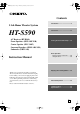
HT-S590_En.book Page 1 Thursday, February 2, 2006 2:55 PM Contents Introduction ..................................... 2 5.1ch Home Theater System HT-S590 AV Receiver (HT-R340) Front Speakers (SKF-340F L/R) Center Speaker (SKC-340C) Surround Speakers (SKM-340S L/R) Subwoofer (SKW-340) Instruction Manual Connection .................................... 19 Turning On & First Time Setup..... 34 Basic Operation Playing your AV components ....... 36 Using the Tuner............................
HT-S590_En.book Page 2 Thursday, February 2, 2006 2:55 PM WARNING: TO REDUCE THE RISK OF FIRE OR ELECTRIC SHOCK, DO NOT EXPOSE THIS APPARATUS TO RAIN OR MOISTURE. CAUTION: TO REDUCE THE RISK OF ELECTRIC SHOCK, DO NOT REMOVE COVER (OR BACK). NO USER-SERVICEABLE PARTS INSIDE. REFER SERVICING TO QUALIFIED SERVICE PERSONNEL.
HT-S590_En.book Page 3 Thursday, February 2, 2006 2:55 PM Precautions 1. Recording Copyright—Unless it’s for personal use only, recording copyrighted material is illegal without the permission of the copyright holder. 2. AC Fuse—The AC fuse inside the unit is not userserviceable. If you cannot turn on the unit, contact your Onkyo dealer. 3. Care—Occasionally you should dust the unit all over with a soft cloth. For stubborn stains, use a soft cloth dampened with a weak solution of mild detergent and water.
HT-S590_En.book Page 4 Thursday, February 2, 2006 2:55 PM Precautions—Continued Speaker Precautions For British models Placement Replacement and mounting of an AC plug on the power supply cord of this unit should be performed only by qualified service personnel.
HT-S590_En.book Page 5 Thursday, February 2, 2006 2:55 PM Features HT-R340 AV Receiver • • • • • • • • • • • • • • • • • • • 100 W/channel into 6 ohms (FTC) 100 W/channel into 6 ohms (DIN) 120 W/channel into 6 ohms (JEITA) Dolby*1 Digital and Dolby Pro Logic II DTS and DTS Neo:6*2 5.1 Optimum Gain Volume Circuitry Massive High Current Power Supply (H.C.P.S.
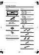
HT-S590_En.book Page 6 Thursday, February 2, 2006 2:55 PM Package Contents Make sure you have the following items: HT-R340 HTP-340 Front speakers (SKF-340F L/R) HT-R340 Center speaker (SKC-340C) Remote controller & two batteries (AA/R6) Surround speakers (SKM-340S) (American type shown) Indoor FM antenna (Connector type varies from country to country.) Subwoofer (SKW-340) AM loop antenna (Red) (White) Speaker cable for front speakers 15 ft. (4.
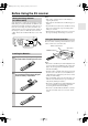
HT-S590_En.book Page 7 Thursday, February 2, 2006 2:55 PM Before Using the AV receiver Setting the Voltage Selector (on some models) Some models have a voltage selector switch for compatibility with power systems around the world. Before you plug in this model, make sure that the voltage selector is set to the correct voltage for your area. If it isn’t, use a small screwdriver to set it as appropriate. For example, if the voltage in your area is 120 volts, set the selector to “120V.
HT-S590_En.
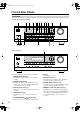
HT-S590_En.book Page 9 Thursday, February 2, 2006 2:55 PM Front & Rear Panels—Continued J MEMORY button (39) N PHONES jack (42) This button is used when storing or deleting radio presets. This 1/4-inch phone jack is for connecting a standard pair of stereo headphones for private listening. K TUNING MODE button (38) O SPEAKERS A & B buttons (36) This button is used to select the Auto or Manual tuning mode.
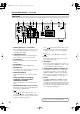
HT-S590_En.book Page 10 Thursday, February 2, 2006 2:55 PM Front & Rear Panels—Continued Rear Panel 1 9 B J K 3 4 5 L 6 7 8 M A DIGITAL IN OPTICAL 1, 2 & COAXIAL These optical and coaxial jacks can be used to connect a CD or DVD player and other components with digital audio outputs. B COMPONENT VIDEO A DVD player, TV, or other component that supports component video can be connected here. C AM ANTENNA These push terminals are for connecting an AM antenna.
HT-S590_En.book Page 11 Thursday, February 2, 2006 2:55 PM Speaker Package Front, Center, Surround, & Subwoofer speakers (SKF-340F, SKC-340C, SKM-340S, SKW-340) A Speaker terminals ■ Rear These push terminals are for connecting the speaker to the HT-R340 with the supplied speaker cables. The supplied speaker cables are color-coded for easy identification. Simply connect each cable to the same-colored positive speaker terminal.
HT-S590_En.book Page 12 Thursday, February 2, 2006 2:55 PM Remote Controller How to Use the Remote Controller Including the AV receiver, the remote controller can be used to control up to six different components. The remote controller has a specific operating mode for use with each type of component. Modes are selected by using the five REMOTE MODE buttons. ■ RECEIVER/TAPE Mode In RECEIVER/TAPE mode, you can control the AV receiver and an Onkyo cassette recorder connected via .
HT-S590_En.book Page 13 Thursday, February 2, 2006 2:55 PM Remote Controller—Continued For detailed information, see the pages in parentheses. O MUTING button (43) This button is used to mute the AV receiver. A ON/STANDBY button (34) P SETUP button (48, 50–53) This button is used to set the AV receiver to On or Standby. B INPUT SELECTOR buttons (36) These buttons are used to select the input sources.
HT-S590_En.book Page 14 Thursday, February 2, 2006 2:55 PM Remote Controller—Continued A ON/STANDBY button DVD Mode This button sets the DVD player to On or Standby. To select your DVD player as the input source, press: RECEIVER 6 DVD B Number buttons These buttons are used to enter title, chapter, and track numbers and to enter times for locating specific points in time. C DISC +/– button This button selects discs on a DVD changer.
HT-S590_En.book Page 15 Thursday, February 2, 2006 2:55 PM Remote Controller—Continued A ON/STANDBY button CD Mode This button sets the CD player to On or Standby. To select your CD player as the input source, press: RECEIVER 9 B Number buttons These buttons are used to enter track numbers and to enter times for locating specific points in time. C DISC +/– button CD This button selects discs on a CD changer.
HT-S590_En.book Page 16 Thursday, February 2, 2006 2:55 PM Remote Controller—Continued A ON/STANDBY button MD, & CDR Mode This button sets the MD/CD recorder to On or Standby. To select your MiniDisc or CD recorder as the input source, press: RECEIVER MD or CD recorder 7 TAPE B Number buttons These buttons are used to enter track numbers and to enter times for locating specific points in time. The [+10] button is used to enter numbers above 10.
HT-S590_En.book Page 17 Thursday, February 2, 2006 2:55 PM Remote Controller—Continued A ON/STANDBY button HDD Mode This button sets the HDD component to On or Standby. To select your HDD component as the input source, press: RECEIVER or 7 3 This button selects the next or previous album on an HDD component. C PLAYLIST [ V3 TAPE B ALBUM +/– button * You must change the Input Display (see page 35). To set the remote controller to HDD mode, press the [HDD] REMOTE MODE button.
HT-S590_En.book Page 18 Thursday, February 2, 2006 2:55 PM Remote Controller—Continued A Play [ ] button TAPE Mode This button is used to start playback. To select your Cassette deck as the input source, press: RECEIVER ]/[ ] buttons The Rewind [ ] button is used to start rewind. The FF [ ] button is used to start fast forward. TAPE mode is used to control an Onkyo cassette recorder connected to the AV receiver via . To set the remote controller to TAPE mode, press the [RECEIVER] REMOTE MODE button.
HT-S590_En.book Page 19 Thursday, February 2, 2006 2:55 PM Enjoying Home Theater Speaker Sets A and B You can use two sets of speakers with the AV receiver: speaker set A and speaker set B. Speaker set A should be used in your main listening room for up to 5.1-channel playback. *While speaker set B is on, speaker set A is reduced to 2.1-channel playback. Speaker set B can be used in another room and offers 2-channel stereo playback.
HT-S590_En.book Page 20 Thursday, February 2, 2006 2:55 PM Connecting Your Speakers Speaker Connection Precautions Read the following before connecting your speakers: • You can connect speakers with an impedance of 6 ohms or higher. If you use speakers with a lower impedance, and use the amplifier at high volume levels for a long period of time, the built-in protection circuit may be activated. • Disconnect the power cord from the wall outlet before making any connections.
HT-S590_En.book Page 21 Thursday, February 2, 2006 2:55 PM Connecting Your Speakers—Continued Wall Mounting Using Speaker Mounts/Brackets The speakers can easily be wall mounted by using the keyhole slots. To prevent the speaker from vibrating against the wall, attach four of the supplied spacers to the keyhole fins on the rear of each speaker. To mount the front or surround speakers vertically, use the keyhole slot shown to hang each speaker on a screw that’s securely screwed into the wall.
HT-S590_En.book Page 22 Thursday, February 2, 2006 2:55 PM Connecting Antenna This section explains how to connect the supplied indoor FM antenna and AM loop antenna, and how to connect commercially available outdoor FM and AM antennas. The AV receiver won’t pick up any radio signals without any antenna connected, so you must connect the antenna to use the tuner. AM antenna push terminals FM antenna jack Connecting the Indoor FM Antenna The supplied indoor FM antenna is for indoor use only.
HT-S590_En.book Page 23 Thursday, February 2, 2006 2:55 PM Connecting Antenna—Continued Connecting an Outdoor FM Antenna Connecting an Outdoor AM Antenna If you cannot achieve good reception with the supplied indoor FM antenna, try a commercially available outdoor FM antenna instead. If good reception cannot be achieved using the supplied AM loop antenna, an outdoor AM antenna can be used in addition to the loop antenna, as shown.
HT-S590_En.book Page 24 Thursday, February 2, 2006 2:55 PM Connecting Your Components AV Connection Color Coding About AV Connections RCA-type AV connections are usually color coded: red, white, and yellow. Use red plugs to connect right-channel audio inputs and outputs (typically labeled “R”). Use white plugs to connect left-channel audio inputs and outputs (typically labeled “L”). And use yellow plugs to connect composite video inputs and outputs.
HT-S590_En.book Page 25 Thursday, February 2, 2006 2:55 PM Connecting Your Components—Continued Connecting Both Audio & Video By connecting both the audio and video outputs of your DVD player and other AV components to the AV receiver, you can select both the audio and video simultaneously simply by selecting the appropriate input source on the AV receiver. : Signal Flow Video Video Audio Audio TV, projector, etc. Speakers (see page 20 for connection information) DVD player, etc.
HT-S590_En.book Page 26 Thursday, February 2, 2006 2:55 PM Connecting Your Components—Continued Connecting a DVD Player Step 1: Video Connection (DVD Player to AV Receiver to TV) A If your TV has component video input jacks, connect your DVD player to the AV receiver’s COMPONENT VIDEO DVD IN jacks. And connect the AV receiver’s COMPONENT VIDEO OUT jacks to your TV. This will provide better picture quality than connection B .
HT-S590_En.book Page 27 Thursday, February 2, 2006 2:55 PM Connecting Your Components—Continued Step 2: Audio Connection a If your DVD player has a coaxial digital audio output jack, connect it to the AV receiver’s DIGITAL IN COAXIAL jack. You can enjoy Dolby and DTS listening modes with this connection.
HT-S590_En.book Page 28 Thursday, February 2, 2006 2:55 PM Connecting Your Components—Continued Connecting a VCR Connecting a VCR for Playback Step 1: Video Connection (VCR to AV Receiver to TV) A Connect your VCR’s video output jack to the AV receiver’s VIDEO 1 IN jack and connect the AV receiver’s MONITOR OUT jack to your TV’s video input jack.
HT-S590_En.book Page 29 Thursday, February 2, 2006 2:55 PM Connecting Your Components—Continued Connecting a VCR for Recording Step 1: Video Connection A Connect the AV receiver’s VIDEO 1 OUT jack to your VCR’s video input jack. Step 2: Audio Connection a Connect the AV receiver’s VIDEO 1 OUT L/R jacks to your VCR’s audio input jacks.
HT-S590_En.book Page 30 Thursday, February 2, 2006 2:55 PM Connecting Your Components—Continued Connecting a Satellite, Cable, Set-top Box, or Other Video Source Step 1: Video Connection A Connect your set-top box’s video output jack to the AV receiver’s VIDEO 2 IN jack and connect the AV receiver’s MONITOR OUT jack to your TV’s video input jack.
HT-S590_En.book Page 31 Thursday, February 2, 2006 2:55 PM Connecting Your Components—Continued Connecting a CD Player or Turntable ■ CD Player or Turntable with Built-in Phono Preamp a Connect your CD player’s analog audio output jacks, or your turntable with built-in phono preamp’s audio output jacks to the AV receiver’s CD IN L/R jacks. With connection a , you can listen to and record audio from the CD player or turntable.
HT-S590_En.book Page 32 Thursday, February 2, 2006 2:55 PM Connecting Your Components—Continued Connecting an HDD-compatible Component (Audio Only) As of this printing, the Onkyo Remote Interactive Dock is the only HDD-compatible component available. Connect your HDD-compatible component’s analog audio output jacks to the AV receiver’s VIDEO 3 IN L/R jacks or TAPE IN L/R jacks. Notes: • Connect the HDD-compatible component’s video output directly to a video input on your TV.
HT-S590_En.book Page 33 Thursday, February 2, 2006 2:55 PM Connecting Your Components—Continued Connecting Onkyo Components Step 1: Make sure that each Onkyo component is connected to the AV receiver with an analog audio cable. Step 2: Make the connection. Step 3: If you’re using an MD, CDR, or HDD component, change the input Display (see page 35).
HT-S590_En.
HT-S590_En.
HT-S590_En.
HT-S590_En.book Page 37 Thursday, February 2, 2006 2:55 PM Playing Your AV Components—Continued Using the Multichannel Input You can display various information about the current input source as follows.
HT-S590_En.book Page 38 Thursday, February 2, 2006 2:55 PM Using the Tuner Listening to the Radio Tuning into Radio Stations TUNING MODE TUNING TUNING / PRESET ■ Auto Tuning Mode 1 TUNING MODE MASTER VOLUME STANDBY/ON ENTER Press the [TUNING MODE] button so that the AUTO indicator appears on the display.
HT-S590_En.
HT-S590_En.book Page 40 Thursday, February 2, 2006 2:55 PM Using the Tuner—Continued Using RDS (European models only) RDS only works with European models and only in areas where RDS broadcasts are available. When tuned into an RDS station, the RDS indicator appears. RDS indicator ■ What is RDS? RDS stands for Radio Data System and is a method of transmitting data in FM radio signals. It was developed by the European Broadcasting Union (EBU) and is available in most European countries.
HT-S590_En.book Page 41 Thursday, February 2, 2006 2:55 PM Using the Tuner—Continued Displaying Radio Text (RT) 4 To start the search, press [ENTER]. The AV receiver searches until it finds a station of the type you specified, at which point it stops briefly before continuing with the search.
HT-S590_En.book Page 42 Thursday, February 2, 2006 2:55 PM Common Functions This chapter explains functions that can be used with any input source.
HT-S590_En.book Page 43 Thursday, February 2, 2006 2:55 PM Common Functions—Continued Using the Sleep Timer ON/STANDBY REMOTE MODE RECEIVER DVD TAPE INPUT SELECTOR 1 2 3 V1 V2 V3 4 5 6 MULTI CH DVD 7 8 9 TAPE TUNER CD +10 0 CLR --/--- DIMMER SLEEP CH DISC ALBUM CD Press [RECEIVER] first With the sleep timer, you can set the AV receiver so that it automatically turns off after a set period.
HT-S590_En.book Page 44 Thursday, February 2, 2006 2:55 PM Common Functions—Continued Adjusting Speaker Levels ON/STANDBY REMOTE MODE RECEIVER DVD TAPE INPUT SELECTOR 1 2 3 V1 V2 V3 4 5 6 MULTI CH DVD 7 8 9 TAPE TUNER CD +10 0 CLR --/--- DIMMER SLEEP CH DISC ALBUM Press [RECEIVER] first CD You can adjust the level of each speaker in speaker set A while listening to an input source. These temporary adjustments are cancelled when the AV receiver is set to Standby.
HT-S590_En.book Page 45 Thursday, February 2, 2006 2:55 PM Recording This chapter explains how to record the selected input source to an AV component with recording capability, and how to record audio and video from two different sources. Recording the Input Source You can record only to AV components that are connected to the TAPE OUT or VIDEO 1 OUT jacks. See pages 24–33 for information on connecting your AV components to the AV receiver.
HT-S590_En.book Page 46 Thursday, February 2, 2006 2:55 PM Using the Listening Modes Selecting Listening Modes RETURN SETUP See “About the Listening Modes” on page 47 for detailed information about the listening modes. SURROUND • The Dolby Digital and DTS listening modes can only be selected if your DVD player is connected to the AV receiver with a digital audio connection (coaxial or optical). • Listening mode availability depends on the format of the current input signal.
HT-S590_En.book Page 47 Thursday, February 2, 2006 2:55 PM Using the Listening Modes—Continued About the Listening Modes With its built-in surround-sound decoders and DSP programs, the AV receiver can transform your home listening room into a movie theater or concert hall. This illustration shows which speakers are active in each listening mode.
HT-S590_En.book Page 48 Thursday, February 2, 2006 2:55 PM Adjusting the Listening Modes 2 ON/STANDBY Use the Up and Down [ ]/[ ] buttons to select “4. Audio Adjust,” and then press the [ENTER] button. REMOTE MODE RECEIVER DVD RECEIVER TAPE INPUT SELECTOR 1 2 3 V1 V2 V3 4 5 6 MULTI CH DVD 7 8 9 TAPE TUNER CD +10 0 CLR --/--- DIMMER SLEEP CH DISC ALBUM CD MD CDR ENTER HDD VOL 3 Use the Left and Right [ ]/[ ] buttons to change the settings.
HT-S590_En.book Page 49 Thursday, February 2, 2006 2:55 PM Adjusting the Listening Modes—Continued PLII Music Mode Settings These settings apply to only 2-channel (stereo) sources. ■ Panorama With this function, you can broaden the width of the front stereo image when using the Pro Logic II Music listening mode. On: Panorama function on. Off: Panorama function off (default). ■ Dimension With this setting, you can move the sound field forward or backward when using the Pro Logic II Music listening mode.
HT-S590_En.book Page 50 Thursday, February 2, 2006 2:55 PM Advanced Setup Advanced Speaker Settings ON/STANDBY 3 Use the Up and Down [ ]/[ ] buttons to select “2. SP Distance,” and then press the [ENTER] button.
HT-S590_En.book Page 51 Thursday, February 2, 2006 2:55 PM Advanced Setup—Continued Speaker Levels With this function, you can adjust the volume of each speaker so that all speakers can be heard equally at the listening position. The speaker levels cannot be adjusted while a pair of headphones is connected, speaker set B is on, or the AV receiver is muted. 1 RECEIVER Press the [RECEIVER] button followed by the [SETUP] button on the remote controller.
HT-S590_En.book Page 52 Thursday, February 2, 2006 2:55 PM Advanced Setup—Continued Speaker Configuration, Crossover Frequency, and Double Bass settings only need to be changed if you’re not using the speakers in this package. These settings cannot be changed while headphones are connected, speaker set B is on, or the multichannel DVD input is being used. 4 Note: • If the Subwoofer setting in step 3 is set to No, this setting is fixed at Large and does not appear.
HT-S590_En.book Page 53 Thursday, February 2, 2006 2:55 PM Advanced Setup—Continued Crossover Frequency This setting only applies to the speakers that you specified as Small in the “Speaker Configuration” on page 52. To get the best bass performance from your speaker system, you need to set the crossover frequency according to the size and frequency response of your speakers. 7 Use the Down [ ] button to select “Crossover,” and then use the Left and Right [ ]/[ ] buttons to select a crossover frequency.
HT-S590_En.book Page 54 Thursday, February 2, 2006 2:55 PM Advanced Setup—Continued Digital Input Signal Formats Correcting Sound and Picture Sync The following table shows the display indicators for each supported digital signal format. Format Display Dolby Digital When using progressive scanning on your DVD player, you may find that the picture and sound are out of sync. With this setting, you can correct this by delaying the audio signals. You can set it to 0, 20, or 40 milliseconds.
HT-S590_En.book Page 55 Thursday, February 2, 2006 2:55 PM Troubleshooting If you have any trouble using the AV receiver, look for a solution in this section. If you can’t resolve the issue yourself, try resetting the AV receiver before contacting your Onkyo dealer. To reset the AV receiver to its factory defaults, turn it on and, while holding down the [VIDEO 1] button, press the [STANDBY/ON] button. “Clear” will appear on the display and the AV receiver will enter Standby mode.
HT-S590_En.book Page 56 Thursday, February 2, 2006 2:55 PM Troubleshooting—Continued • On the AV receiver, the subwoofer setting in the speaker configuration is set to No. Set the subwoofer setting to Yes. There’s no sound with a certain signal format? • Check the digital audio output setting on the connected device. On some games consoles, such as those that can play DVDs, the default setting is off. • With some DVD-Video discs, you need to select an audio output format from a menu. Can’t get 5.
HT-S590_En.book Page 57 Thursday, February 2, 2006 2:55 PM Troubleshooting—Continued Recording Can’t record? • On your recorder, make sure the correct input is selected. • To prevent signal loops and damage to the AV receiver, input signals are not fed through to outputs with the same name (e.g., TAPE IN to TAPE OUT, or VIDEO 1 IN to VIDEO 1 OUT).
HT-S590_En.book Page 58 Thursday, February 2, 2006 2:55 PM Specifications Amplifier Section General Rated Output Power North American (FTC): (FL, FR, C, SL, SR) 95 watts minimum continuous power per channel, 8 ohm loads, 2 channels driven at 1 kHz, with a maximum total harmonic distortion of 0.7% (Subwoofer) 105 watts minimum continuous power per channel, 8 ohm loads, 1 channel driven at 80 kHz, with a maximum total harmonic distortion of 0.
HT-S590_En.book Page 59 Thursday, February 2, 2006 2:55 PM Specifications—Continued 5.
HT-S590_En.book Page 60 Thursday, February 2, 2006 2:55 PM Sales & Product Planning Div. : 2-1, Nisshin-cho, Neyagawa-shi, OSAKA 572-8540, JAPAN Tel: 072-831-8023 Fax: 072-831-8124 ONKYO U.S.A. CORPORATION 18 Park Way, Upper Saddle River, N.J. 07458, U.S.A. Tel: 201-785-2600 Fax: 201-785-2650 http://www.us.onkyo.com/ ONKYO EUROPE ELECTRONICS GmbH Liegnitzerstrasse 6, 82194 Groebenzell, GERMANY Tel: +49-8142-4401-0 Fax: +49-8142-4401-555 http://www.eu.onkyo.