Contents 7.1ch Home Theater System HT-S7300 AV Receiver (HT-R680) Speaker Package (HTP-780) Universal Port Option Dock for iPod® (UP-A1) HT-S6300 AV Receiver (HT-R680) Speaker Package (HTP-680) Universal Port Option Dock for iPod® (UP-A1) Introduction ...................................2 Connections.................................14 Turning On & Basic Operations ......24 Advanced Operations .................38 Controlling iPod & Other Components............................
Introduction WARNING: TO REDUCE THE RISK OF FIRE OR ELECTRIC SHOCK, DO NOT EXPOSE THIS APPARATUS TO RAIN OR MOISTURE. CAUTION: TO REDUCE THE RISK OF ELECTRIC SHOCK, DO NOT REMOVE COVER (OR BACK). NO USER-SERVICEABLE PARTS INSIDE. REFER SERVICING TO QUALIFIED SERVICE PERSONNEL.
Precautions 1. Recording Copyright—Unless it’s for personal use only, recording copyrighted material is illegal without the permission of the copyright holder. 2. AC Fuse—The AC fuse inside the unit is not user-serviceable. If you cannot turn on the unit, contact your Onkyo dealer. 3. Care—Occasionally you should dust the unit all over with a soft cloth. For stubborn stains, use a soft cloth dampened with a weak solution of mild detergent and water. Dry the unit immediately afterwards with a clean cloth.
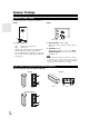
Speaker Precautions Package Contents Placement Make sure you have the following items: • The subwoofer cabinet is made out of wood and is therefore sensitive to extreme temperatures and humidity, do not put it in locations subject to direct sunlight or in humid places, such as near an air conditioner, humidifier, bathroom, or kitchen. • Do not put water or other liquids close to the speakers. If liquid is spilled over the speakers, the drive units may be damaged.
Contents Speaker Package HTP-780 Front speakers (SKF-780 L/R) (➔ 10) Introduction Center speaker (SKC-780) (➔ 10) Surround speakers (SKR-780 L/R) (➔ 10) Surround back speakers (SKB-780 L/R) (➔ 10) Subwoofer (SKW-780) (➔ 10) Speaker cables for front speakers 11 ft. (3.5 m) (White and Red) (➔ 17) Speaker cable for center speaker 10 ft. (3.0 m) (Green) (➔ 17) Speaker cables for surround speakers 26 ft. (8.0 m) (Blue and Gray) (➔ 17) Speaker cables for surround back speakers 26 ft. (8.
Features AV Receiver HT-R680 • 130 Watts/Channel @ 6 ohms • WRAT–Wide Range Amplifier Technology (5 Hz to 100 kHz bandwidth) • Optimum Gain Volume Circuitry • H.C.P.S. (High Current Power Supply) Massive High Power Transformer • HDMI (Ver.1.4 with Audio Return Channel, 3D), DeepColor, x.v.
Speaker Package HTP-680 SKF-680 L/R 2-Way Front Speakers • 4" (10 cm) Cone woofer • 1" (2.5 cm) Balanced dome tweeter • Max. input power: 130 W • Gloss Finished • 6-ohm impedance • Color-coded speaker terminals and speaker cable SKC-680 2-Way Center Speaker • 4" (10 cm) Cone woofer • 1" (2.5 cm) Balanced dome tweeter • Max.
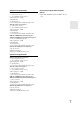
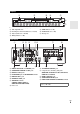
Front & Rear Panels Front Panel a b cd e fg q r h i j klm n s o p t u v w The actual front panel has various logos printed on it. They are not shown here for clarity. The page numbers in parentheses show where you can find the main explanation for each item.
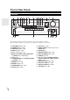
Display a b c d e f g For detailed information, see the pages in parentheses.
Speaker Package Subwoofer (SKW-770/780) For detailed information, see the pages in parentheses. ■ Front ■ Rear a To AC outlet a Standby/On indicator Red: Blue: b c b OUTPUT LEVEL control (➔ 25) This control is used to adjust the volume of the subwoofer. Subwoofer in standby mode Subwoofer on With the Auto Standby function, the SKW-770/780 automatically turns on when an input signal is detected in Standby mode.
■ HTP-780 (SKF-780, SKC-780, SKR-780, SKB-780) SKF-780 SKC-780 a b a Rear Front b SKR-780/SKB-780 a b Front Front Rear Rear a Keyhole slots These keyhole slots can be used to wall-mount the speaker. See “Wall Mounting” for mounting instructions (➔ 14). b Speaker terminals These push terminals are for connecting the speaker to the HT-R680 with the supplied speaker cables. The supplied speaker cables are color-coded for easy identification.
Remote Controller Controlling the AV Receiver a To control the AV receiver, press RECEIVER to select Receiver mode. You can also use the remote controller to control Onkyo Blu-ray Disc/DVD player, CD player and other components. See “Entering Remote Control Codes” for more details (➔ 61). h b *1 i For detailed information, see the pages in parentheses.
About Home Theater Enjoying Home Theater Thanks to the AV receiver’s superb capabilities, you can enjoy surround sound with a real sense of movement in your own home—just like being in a movie theater or concert hall. With Blu-ray Discs or DVDs, you can enjoy DTS and Dolby Digital. With analog or digital TV, you can enjoy Dolby Pro Logic IIx, DTS Neo:6, or Onkyo’s original DSP listening modes. Speaker illustrations are based on HTP-680.
Connections Connecting the AV Receiver Attaching the Speaker Bases ■ SKF-780 Before you connect the speakers, attach the supplied speaker base to each SKF-780. 1. Turn the speaker upside down with the protection cover attached. 2. Align the speaker base while the arrow mark is headed in the same direction as the speaker’s face. Be careful not to tip over the speaker. 3. Align the screw holes on the speaker base with those on the bottom of each speaker, and affix the speaker base using the supplied screws.
■ SKC-780 Keyhole slot for wall mounting Using the Stoppers for a More Stable Platform We recommend using the provided stoppers to achieve the best possible sound from your speakers. The stoppers prevent the speakers from moving, providing a more stable platform. 7-7/8" (200 mm) ■ SKF-680, SKR-680, SKB-680, SKC-680 Use rubber stoppers for the speakers. Rubber stoppers Caution • A mounting screw’s ability to support a speaker depends on how well it’s anchored to the wall.
• Make sure the metal core of the wire does not have contact with the AV receiver’s rear panel. Doing so may damage the AV receiver. Connecting Your Speakers Speaker Configuration The following table indicates the channels you should use depending on the number of speakers that you have. For 7.1-channel surround-sound playback, you need 7 speakers and a powered subwoofer.
Connecting the Speaker Cables Screw-type speaker terminals Strip 1/2" to 5/8" (12 to 15 mm) of insulation from the ends of the speaker cables, and twist the bare wires tightly, as shown. (Supplied speaker cables are already stripped.) 1/2" to 5/8"(12 to 15 mm) Using Banana Plugs • If you are using banana plugs, tighten the speaker terminal before inserting the banana plug. • Do not insert the speaker code directly into the center hole of the speaker terminal.
About AV Connections Connected image with AV components HDMI cable Other cables : Video & Audio AV receiver TV, projector, etc. Blu-ray Disc/ DVD player : Video : Audio AV receiver Game console TV, projector, etc. Blu-ray Disc/ DVD player • Before making any AV connections, read the manuals supplied with your AV components. • Don’t connect the power cord until you’ve completed and double-checked all AV connections.
Connecting Your Components with HDMI VCR or DVD recorder/Digital Video Recorder Game console TV, projector, etc. Satellite, cable, set-top box, etc. Blu-ray Disc/DVD player Connect your components to the appropriate jacks. The default input assignments are shown below. ✔: Assignment can be changed (➔ 39). Jack Input Output Signal Components Assignable Audio/Video Blu-ray Disc/DVD player ✔ HDMI IN 2 VCR or DVD recorder/Digital Video Recorder ✔ HDMI IN 3 Satellite, cable, set-top box, etc.
Connecting Your Components The on-screen setup menus appear only on a TV that is connected to the HDMI OUT. If your TV is connected to the MONITOR OUT V or the COMPONENT VIDEO OUT, use the AV receiver’s display when changing settings. Front Rear A C B D E Connect your components to the appropriate jacks. The default input assignments are shown below. ✔: Assignment can be changed (➔ 40). No.
Connecting Onkyo u Components Step 1: Make sure that each Onkyo component is connected with an analog audio cable (connection D in the hookup examples) (➔ 20). Step 2: Make the u connection (see illustration below). Step 3: If you’re using an RI Dock, or cassette tape deck, change the Input Display (➔ 27).
Connecting Antenna This section explains how to connect the supplied indoor FM antenna and AM loop antenna. The AV receiver won’t pick up any radio signals without any antenna connected, so you must connect the antenna to use the tuner. Caution • Be careful that you don’t injure yourself when using thumbtacks. Insert the plug fully into the jack. Push. Insert wire. Release. Assembling the AM loop antenna. Thumbtacks, etc.
Which Connections Should I Use? The AV receiver supports several connection formats for compatibility with a wide range of AV equipment. The format you choose will depend on the formats supported by your components. Use the following sections as a guide. The on-screen setup menus appear only on a TV that is connected to the HDMI OUT. If your TV is connected to the MONITOR OUT V or the COMPONENT VIDEO OUT, use the AV receiver’s display when changing settings.
Turning On & Basic Operations Turning On/Off the AV Receiver ON/STANDBY STANDBY indicator ON/STANDBY RECEIVER Turning On Press ON/STANDBY on the front panel. or Press RECEIVER followed by ON/STANDBY on the remote controller. The AV receiver comes on, the display lights, and the STANDBY indicator goes off. Turning Off Press ON/STANDBY on the front panel or the remote controller. The AV receiver will enter Standby mode.
Basic Operations The on-screen menus appear only on a TV that is connected to the HDMI OUT. If your TV is connected to the MONITOR OUT V or the COMPONENT VIDEO OUT, use the AV receiver’s display when changing settings. ■ Adjusting the subwoofer volume level Use the subwoofer’s OUTPUT LEVEL control to adjust the volume of the subwoofer. Because our ears are less sensitive to very low bass sounds, there’s a temptation to set the level of the subwoofer too high.
Using the Music Optimizer The Music Optimizer function enhances the sound quality of compressed music files. Selecting Speaker Layout You can prioritize which speakers you want to use. Press RECEIVER followed by SP LAYOUT repeatedly. `Speaker Layout:FH: The sound from front high speakers is output by priority. `Speaker Layout:SB: The sound from surround back speakers is output by priority. Press MUSIC OPTIMIZER on the front panel. The M.Opt indicator lights on the display.
2 Use q/w/e/r to make the desired selection. ■ Audio*1 ` You can change the following settings: “Bass”, “Treble”, “Subwoofer Level”, “Center Level”, “Dynamic EQ”, “Dynamic Volume”, “Late Night”, “Music Optimizer”, “Cinema filter” and “Audio Selector”. See also: • “Audyssey” (➔ 44) • “Using the Audio Settings” (➔ 50) Changing the Input Display When you connect an u-capable Onkyo component, you must configure the input display so that u can work properly. This setting can be done only from the front panel.
Audyssey 2EQ® Room Correction and Speaker Setup With the supplied calibrated microphone, Audyssey 2EQ automatically determines the number of speakers connected, their size for purposes of bass management, optimum crossover frequencies to the subwoofer (if present), and distances from the primary listening position. Audyssey 2EQ then removes the distortion caused by room acoustics by capturing room acoustical problems over the listening area in both the frequency and time domain.
7 Use q/w to select an option, and then press ENTER. 2EQ: Auto Setup - - Review Speaker Configuration - Subwoofer Front Center Surround Front High Surr Back Surr Back Ch Yes 40Hz 40Hz 100Hz 100Hz 120Hz 2ch TV Save Cancel The options are: ` Save: Save the calculated settings and exit Audyssey 2EQ® Room Correction and Speaker Setup. ` Cancel: Cancel Audyssey 2EQ Room Correction and Speaker Setup.
Listening to the Radio This section describes the procedure using the buttons on the front panel unless otherwise specified. ■ Manual tuning mode 1 2 Using the Tuner With the built-in tuner you can enjoy AM and FM radio stations. You can store your favorite stations as presets for quick selection. This model changes FM/AM frequency in 200/10kHz (or 50/9kHz) steps. Press TUNING MODE so that the AUTO indicator goes off on the display. Press and hold TUNING q/w.
Presetting FM/AM Stations You can store a combination of up to 40 of your favorite FM/AM radio stations as presets. 1 2 3 4 Tune into the FM/AM station that you want to store as a preset. See the previous section. Press MEMORY. The preset number flashes. While the preset number is flashing (about 8 seconds), use PRESET e/r to select a preset from 1 through 40. Press MEMORY again to store the station or channel. The station or channel is stored and the preset number stops flashing.
Recording This section explains how to record the selected input source to a component with recording capability, and how to record audio and video from different sources. Connecting a Recording Component L Here you can record audio and video from completely separate sources, allowing you to overdub audio onto your video recordings. This function takes advantage of the fact that when an audio-only input source (TV/CD) is selected, the video input source remains unchanged.
Using the Listening Modes Selecting Listening Modes See “About Listening Modes” for detailed information about the listening modes (➔ 34). Listening Mode Buttons Press RECEIVER first. MOVIE/TV, MUSIC, GAME MUSIC MOVIE/TV GAME STEREO MOVIE/TV button This button selects the listening modes intended for use with movies and TV. MUSIC button This button selects the listening modes intended for use with music. GAME button This button selects the listening modes intended for use with video games.
About Listening Modes The AV receiver’s listening modes can transform your listening room into a movie theater or concert hall, with high fidelity and stunning surround sound. Explanatory Notes Speaker illustrations are based on HTP-680. ab c ij SP LAYOUT f LISTENING MODE de gh a b Front speakers c Center speaker d e Surround speakers f Subwoofer g h Surround back speakers i j Front high speakers ■ Input Source The following audio formats are supported by the listening mode.
Listening Modes Listening Mode Description Input Source Direct Speaker Layout In this mode, audio from the input source is output without surround-sound A processing. The “Sp Config” (presence of speakers), “Sp Distance” and S D i r e c t d i o P P “A/V Sync” settings are enabled, but much of the processing set via AUDIO D is disabled. See “Advanced Setup” for more details (➔ 38). F G H ZXC N*1 Stereo Sound is output by the front left and right speakers and subwoofer.
Listening Mode Description Input Source Dolby Digital In this mode, audio from the input source is output without surround-sound D processing. “Sp Config” (presence of speakers), “Crossover”, “Sp DisD o l b y c D i o P P tance”, “A/V Sync” and much of the processing set via AUDIO are enabled. Dolby Digital Plus*5 See “Advanced Setup” for more details (➔ 38).
Onkyo-Original DSP Listening Modes Listening Mode Description Orchestra Suitable for classical or operatic music, this mode emphasizes the surround A channels in order to widen the stereo image, and simulates the natural rever- S beration of a large hall. D Suitable for acoustic instruments, vocals, and jazz, this mode emphasizes the G front stereo image, giving the impression of being right in front of the stage.
Advanced Operations Advanced Setup On-screen Setup Menus Common Procedures in Setup Menu The on-screen setup menus appear only on a TV that is connected to the HDMI OUT. If your TV is connected to the composite video MONITOR OUT or the COMPONENT VIDEO OUT, use the AV receiver’s display when changing settings. This manual describes the procedure using the remote controller unless otherwise specified. Remote indicator RECEIVER ENTER q/w/e/r a b c d e f g h i 1. 2. 3. 4. 5. 6. 7. 8. 9.
Explanatory Notes a b c Main menu Composite video, component video Speaker Setup IN ■ Subwoofer ` Yes: Select if a subwoofer is connected. ` No: Select if no subwoofer is connected. a Menu selection b Setting target c Setting options (default setting underlined) Input/Output Assign Main Menu Input/Output Assign Monitor Out You can specify the output resolution for the HDMI OUT and have the AV receiver upconvert the picture resolution as necessary to match the resolution supported by your TV.
Component Video Input If you connect a video component to a component video input, you must assign that input to an input selector. For example, if you connect your Blu-ray Disc/DVD player to COMPONENT VIDEO IN 2, you must assign “IN2” to the “BD/DVD” input selector. Here are the default assignments.
Speaker Configuration This setting is set automatically by Audyssey 2EQ® Room Correction and Speaker Setup function (➔ 28). With these settings, you can specify which speakers are connected and a crossover frequency for each speaker. Specify “Full Band” for speakers that can output low frequency bass sounds adequately, for example, speakers with a good sized woofer. For smaller speakers, specify a crossover frequency.
Level Calibration This setting is set automatically by Audyssey 2EQ® Room Correction and Speaker Setup function (➔ 28). Here you can adjust the level of each speaker with the built-in test tone so that the volume of each speaker is the same at the listening position. ■ Left, Front High Left, Center*1, Front High Right, Right, Surr Right, Surr Back Right, Surr Back Left, Surr Left ` –12dB to 0dB to +12dB in 1 dB step. ■ Subwoofer*1 ` –15dB to 0dB to +12dB in 1 dB step.
Dimension `–3 to 0 to +3 With this setting, you can move the sound field forward or backward when using the Dolby Pro Logic IIx Music listening mode. Higher settings move the sound field backward. Lower settings move it forward. If the stereo image feels too wide, or there’s too much surround sound, move the sound field forward to improve the balance. Conversely, if the stereo image feels like it’s in mono, or there’s not enough surround sound, move it backward.
Source Setup Items can be set individually for each input selector. Preparation Press the input selector buttons to select an input source. Main menu Source Setup Audyssey When Audyssey 2EQ® Room Correction and Speaker Setup is complete, the “Equalizer” setting (➔ 42) will be set to “Audyssey” and the “Dynamic EQ” will be set to “On”. ■ Dynamic EQ ` Off: Audyssey Dynamic EQ® off. ` On: Audyssey Dynamic EQ on. The Dynamic EQ indicator will light (➔ 9).
About Audyssey Dynamic Volume® Audyssey Dynamic Volume solves the problem of large variations in volume level between television programs, commercials, and between the soft and loud passages of movies. Dynamic Volume looks at the preferred volume setting by the user and then monitors how the volume of program material is being perceived by listeners in real time to decide whether an adjustment is needed.
To correct a character: 1 2 3 ` Wide Zoom: Use q/w/e/r to select “ ”(Left) or “ ”(Right), and then press ENTER. Press ENTER several times to select the incorrect character (The cursor moves one letter each time ENTER is pressed). Use q/w/e/r to select the correct character, and then press ENTER. Note • To name a radio preset, use TUNER to select AM or FM, and then select the preset (➔ 31). To restore a custom name to the default, erase the custom name by entering an empty white space for each letter.
■ Edge Enhancement*2 `0 to +10 With this setting you can adjust the sharpness of edges in the picture. “0” is the softest. “+10” is the sharpest. Main menu 1 ■ Noise Reduction*2 `Off: Noise reduction off. `Low: Low noise reduction. `Mid: Medium noise reduction. `High: High noise reduction. With this setting, you can reduce noise appearing on the screen. 5. Listening Mode Preset 1. 2. 3. 4. 5. 6. 7. 8. ■ Brightness*1*2 `–50 to 0 to +50 With this setting you can adjust the picture brightness.
Miscellaneous Main menu Hardware Setup Miscellaneous Remote ID ■ Maximum Volume ` Off, 30 to 79 With this setting, you can limit the maximum volume. To disable this setting, select “Off”. ■ Remote ID ` 1, 2, or 3 When several Onkyo components are used in the same room, their remote ID codes may overlap. To differentiate the AV receiver from the other components, you can change its remote ID from “1”, to “2” or “3”.
HDMI ■ Audio TV Out `Off: The audio is not output from the HDMI output. `On: The audio is output from the HDMI output. This preference determines whether the incoming audio signal is output from the HDMI OUT. You may want to turn this preference on if your TV is connected to the HDMI OUT and you want to listen to the audio from a connected component through your TV’s speakers. Normally, this should be set to “Off”.
Note • The “Power Control” setting can be set only when the “HDMI Control (RIHD)” setting is set to “On”. • HDMI power control only works with p-compatible components that support it and may not work properly with some components due to their settings or compatibility. • When set to “On”, power consumption will increase.
Speaker Levels Music Optimizer You can adjust the volume of each speaker while listening to an input source. These temporary adjustments are cancelled when the AV receiver is set to Standby. To save the setting you made here, go to “Level Calibration” (➔ 42) before setting the AV receiver to Standby. The Music Optimizer function enhances the sound quality of compressed music files. Use it with music files that use “lossy” compression, such as MP3. ■ Subwoofer Level `–15dB to 0dB to +12dB in 1 dB steps.
Audio Selector You can set priorities of audio output when there are both digital and analog inputs. ■ Audio Selector ` ARC: The audio signal from your TV tuner can be sent to the HDMI OUT of the AV receiver.*1 With this selection the TV’s audio can be automatically selected as a priority among other assignments. ` HDMI: This can be selected when HDMI IN has been assigned as an input source.
Zone 2 In addition to your main listening room, you can also enjoy playback in the other room, or as we call Zone 2. And, you can select a different source for each room. Connecting Your Zone 2 Speakers to an Amp in Zone 2 Connecting Zone 2 There are two ways you can connect Zone 2 speakers: 1. Connect them directly to the AV receiver. 2. Connect them to an amp in Zone 2. Connecting Your Zone 2 Speakers Directly to the AV receiver This setup allows 5.
Setting the Powered Zone 2 If you’ve connected your Zone 2 speakers to the AV receiver, as explained in “Connecting Your Zone 2 Speakers Directly to the AV receiver” (➔ 53), you must set the “Front High/Zone2” setting to “Zone2”. Main menu 1 2 Speaker Setup Using Zone 2 This section explains how to turn Zone 2 on and off, how to select an input source for Zone 2, and how to adjust the volume for Zone 2.
Controlling Zone 2 with the Remote Controller Adjusting the Volume for Zone 2 ■ Operating with the remote controller ON/STANDBY ZONE2 Input selector buttons 1 2 Press ZONE2. Use VOL q/w to adjust the volume. MUTING VOLq/w ■ Operating on the AV receiver 1 1 2 Press ZONE2 and then press ON/STANDBY. Zone 2 turns on, the ZONE 2 indicator lights. To select an input source for Zone 2, press ZONE2, followed by an input selector buttons. To select AM or FM, press the TUNER input selector repeatedly.
Controlling iPod & Other Components Controlling iPod Connecting an Onkyo Dock A B *1 No. Onkyo Dock Cable Note A UP-A1 Dock (Included) (Universal Port Option Dock) — • When UP-A1 Dock that seated iPod is 57 connected, the power consumption on standby mode slightly increases. • You can control your iPod when PORT is selected as the input source. B RI Dock (Not Included) Analog audio (RCA) • See the RI Dock’s instruction manual 58 for more information.
Using the Onkyo Dock • It is recommended that you update your iPod software before using it with this unit. The updater for the iPod software is available at the Apple website. For the latest information on the Onkyo Dock components, see the Onkyo web site at: http://www.onkyo.com Before using the Onkyo Dock components, update your iPod with the latest software, available from the Apple web site.
■ Charging Your iPod models Battery The UP-A1 Dock charges your iPod models battery while your iPod is in the UP-A1 Dock and connected to the UNIVERSAL PORT jack on the AV receiver. While your iPod is seated in the UP-A1 Dock, its battery will be charged when the AV receiver is set to “On” or “Standby”. Note • When UP-A1 Dock that seated iPod is connected, the power consumption on standby mode slightly increases. ■ Status Messages • PORT Reading The AV receiver is checking the connection with the dock.
✔: Available buttons Press the appropriate REMOTE MODE first. Buttons ✔*1 a ON/STANDBY 9 g h i b j c d ✔*5 b TOP MENU ✔ ✔ ✔*3 ✔ d 1, 3, 2, 5, 4, 7, 6 ✔ ✔ e REPEAT RANDOM ✔ ✔ c q/w/e/rENTER PLAYLIST e/r ✔ ✔ ✔*4 ✔*4 f DISPLAY*6 g MUTING ✔*2 ✔ ✔ ✔ h ALBUM +/– ✔ ✔ i VOL q/w ✔ ✔ j MENU k RETURN ✔ PLAY MODE k u Dock f UP-A1 Dock a Onkyo Dock ✔ e • With some iPod models, generations and RI Docks, certain buttons may not work as expected.
Controlling Other Components You can use the AV receiver’s remote controller (RC-764M) to control your other AV components, including those made by other manufacturers. This section explains how to enter the remote control code (with the default underlined) for a component that you want to control: DVD, TV, CD, etc. 5 8–1. Remote Mode Setup TV Category Brand Preprogrammed Remote Control Codes The following REMOTE MODE are preprogrammed with remote control codes for controlling the components listed.
Entering Remote Control Codes 2 You’ll need to enter a code for each component that you want to control. 1 2 Look up the appropriate remote control code in the separate Remote Control Codes list. The codes are organized by category (e.g., DVD player, TV, etc.). While holding down REMOTE MODE to which you want to enter a code, press and hold down DISPLAY (about 3 seconds). The remote indicator lights. Note • Remote control codes cannot be entered for RECEIVER and ZONE 2.
Resetting REMOTE MODE Buttons You can reset a REMOTE MODE to its default remote control code. 1 2 While holding down REMOTE MODE that you want to reset, press and hold down AUDIO until the remote indicator lights (about 3 seconds). Within 30 seconds, press REMOTE MODE again. The remote indicator flashes twice, indicating that the button has been reset. Each of REMOTE MODE is preprogrammed with a remote control code. When a button is reset, its preprogrammed code is restored.
✔: Available buttons Press the appropriate REMOTE MODE first.
Others Troubleshooting If you have any trouble using the AV receiver, look for a solution in this section. If you can’t resolve the issue yourself, contact your Onkyo dealer. If you can’t resolve the issue yourself, try resetting the AV receiver before contacting your Onkyo dealer. To reset the AV receiver to its factory defaults, turn it on and, while holding down VCR/DVR, press ON/ STANDBY. “Clear” will appear on the display and the AV receiver will enter Standby mode.
■ Only the front speakers produce sound When the Stereo or Mono listening mode is selected, — only the front speakers and subwoofer produce sound. Check the Speaker Configuration. 41 ■ Only the center speaker produces sound If you use the Dolby Pro Logic IIx Movie, Dolby Pro — Logic IIx Music, or Dolby Pro Logic IIx Game listening mode with a mono source, such as an AM radio station or mono TV program, the sound is concentrated in the center speaker. Make sure the speakers are configured correctly.
Video Tuner ■ There’s no picture Make sure that all video connecting plugs are pushed 18 in all the way. Make sure that each video component is properly connected. 19, 20, 56 If your TV is connected to the HDMI OUT, select 39 “- - - - -” in the “HDMI Input” setup to watch composite video, and component video sources. If the video source is connected to a component video input, you must assign that input to an input selector, and your TV must be connected to either the HDMI OUT or COMPONENT VIDEO OUT.
To control an Onkyo component that’s not connected 61 via u, point the remote controller at the component. Be sure to enter the appropriate remote control code first. The entered remote control code may not be correct. — If more than one code is listed, try each one. UP-A1 Dock for iPod ■ There’s no sound Make sure your iPod is actually playing. — Make sure your iPod is inserted properly in the Dock. — Make sure the UP-A1 Dock is connected to the UNI- — VERSAL PORT jack on the AV receiver.
■ The following settings can be made for the composite video inputs You must use the buttons on the unit to make these settings. 1. While holding down the input selector button for the input source that you want to set, press SETUP. 2. Use e/r to change the setting. 3. Press the input selector button for the input source that you want to set when you’ve finished. 1 The AV receiver contains a microcomputer for signal processing and control functions.
Specifications AV receiver Amplifier Section General Rated Output Power All channels: Power Supply AC 120 V, 60 Hz Power Consumption 4.9 A Stand-by Power Consumption 0.2 W Dimensions 17-1/8" × 5-15/16" × 12-15/16" (W × H × D) 435 mm × 151.5 mm × 328.
7.1ch Home Theater Speaker Package (HTP-680) ■ Powered Subwoofer (SKW-770) ■ Center Speaker (SKC-680) Type Bass-reflex Input sensitivity/Impedance 140 mV/20 kΩ Maximum output power 290 W (Dynamic power) Frequency response 25 Hz to 150 Hz Cabinet capacity 37 L (1.3 cubic feet) Type 2 Way closed box Impedance 6Ω Maximum input power 130 W Sensitivity 81 dB/W/m Frequency response 60 Hz to 50 kHz Crossover frequency 4 kHz Cabinet capacity 2.1 L (0.
7.1ch Home Theater Speaker Package (HTP-780) ■ Powered Subwoofer (SKW-780) ■ Center Speaker (SKC-780) Type Bass-reflex Input sensitivity/Impedance 140 mV/20 kΩ Maximum output power 290 W (Dynamic power) Frequency response 25 Hz to 150 Hz Cabinet capacity 37 L (1.3 cubic feet) Type 2 Way Bass-reflex Impedance 6Ω Maximum input power 130 W Sensitivity 79 dB/W/m Frequency response 60 Hz–50 kHz Crossover frequency 4 kHz Cabinet capacity 2.8 L (0.
About HDMI Designed to meet the increased demands of digital TV, HDMI (High Definition Multimedia Interface) is a new digital interface standard for connecting TVs, projectors, Blu-ray Disc/DVD players, set-top boxes, and other video components. Until now, several separate video and audio cables have been required to connect AV components.
Using an RIHD-compatible TV, Player, or Recorder p, which stands for Remote Interactive over HDMI, is the name of the system control function found on Onkyo components. The AV receiver can be used with CEC (Consumer Electronics Control), which allows system control over HDMI and is part of the HDMI standard. CEC provides interoperability between various components, however, operation with components other than p-compatible components cannot be guaranteed.
3 ■ How to connect and setup 1 Confirm the connecting and setting. 1. Connect the HDMI OUT jack to the HDMI input jack of the TV. Blu-ray Disc/DVD player, etc. HDMI connection AV receiver DIGITAL AUDIO connection (OPTICAL) HDMI connection TV, projector, etc. 2. Connect the audio output from the TV to the OPTICAL IN 2 jack of the AV receiver using an optical digital cable.
Video Resolution Chart The following tables show how video signals at different resolutions are output by the AV receiver.
Sales & Product Planning Div. : 2-1, Nisshin-cho, Neyagawa-shi, OSAKA 572-8540, JAPAN Tel: 072-831-8023 Fax: 072-831-8163 ONKYO U.S.A. CORPORATION 18 Park Way, Upper Saddle River, N.J. 07458, U.S.A. Tel: 800-229-1687, 201-785-2600 Fax: 201-785-2650 http://www.us.onkyo.com/ ONKYO EUROPE ELECTRONICS GmbH Liegnitzerstrasse 6, 82194 Groebenzell, GERMANY Tel: +49-8142-4401-0 Fax: +49-8142-4401-555 http://www.eu.onkyo.